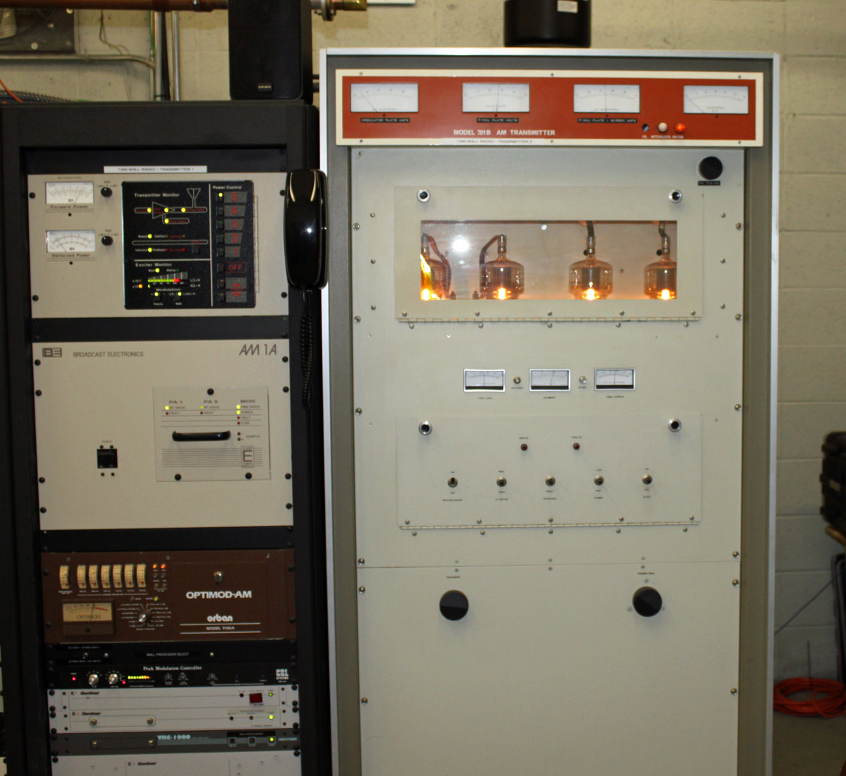
In service as a backup unit at WALL 1340 KHz in Middletown, NY:
WALL 1340 KHz, Middletown NY AM1A on air, 701B into test load
I believe the Cetec transmitter is from the early 70s. I wouldn’t really call it old, we have much older units in the field that are still in backup service. WALL itself has been on the air since 1942 from this site. The tower out back was replaced in the mid ’90s and is 147 degrees tall. It broadcasts the “True Oldies Channel” and is currently owned by Cumulus, soon to be Townsquare.
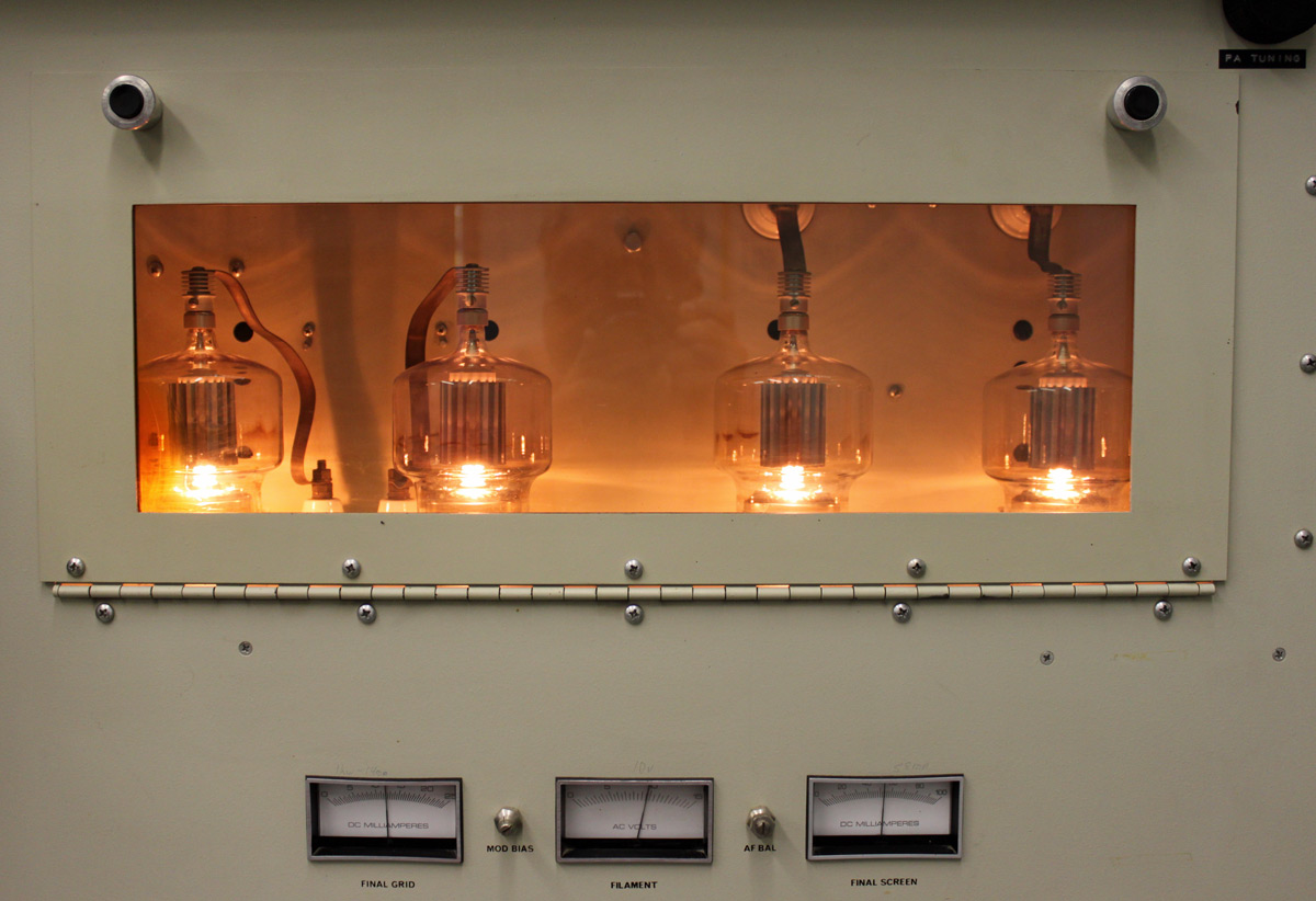
Cetec 701B tube deck. 4-500As.
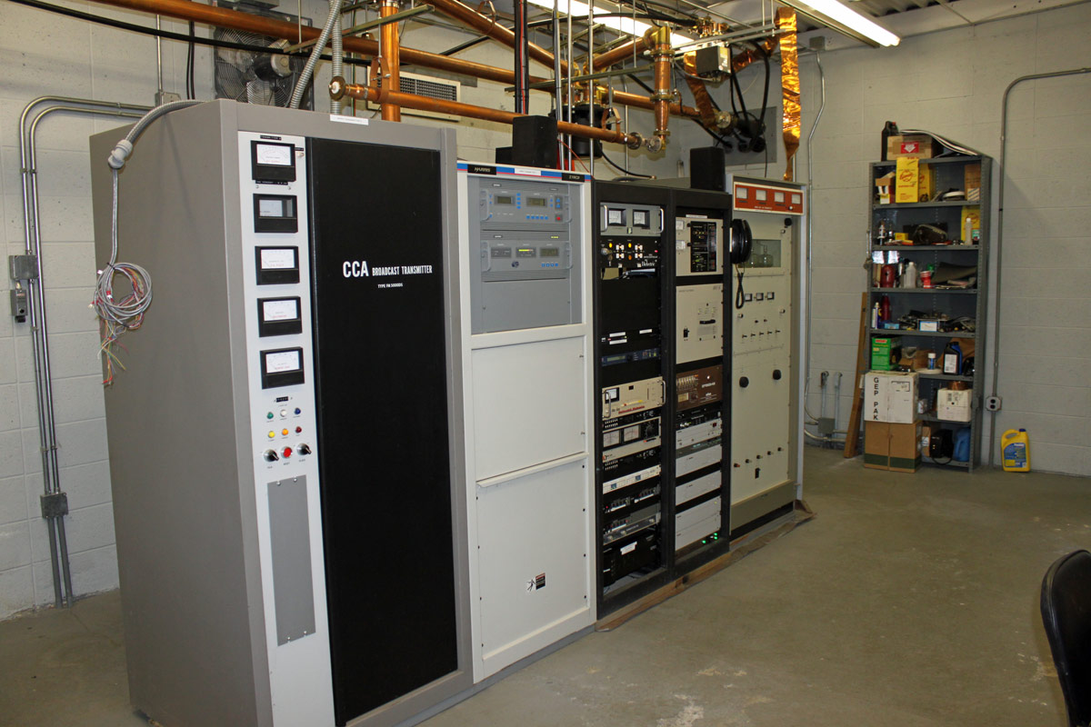
The site is also home to sister station WRRV (92.7 MHz) which has a side mounted antenna near the top of the WALL tower. We are currently reconnecting the CCA transmitter as the backup for WRRV. That unit is also from the early 1970’s.
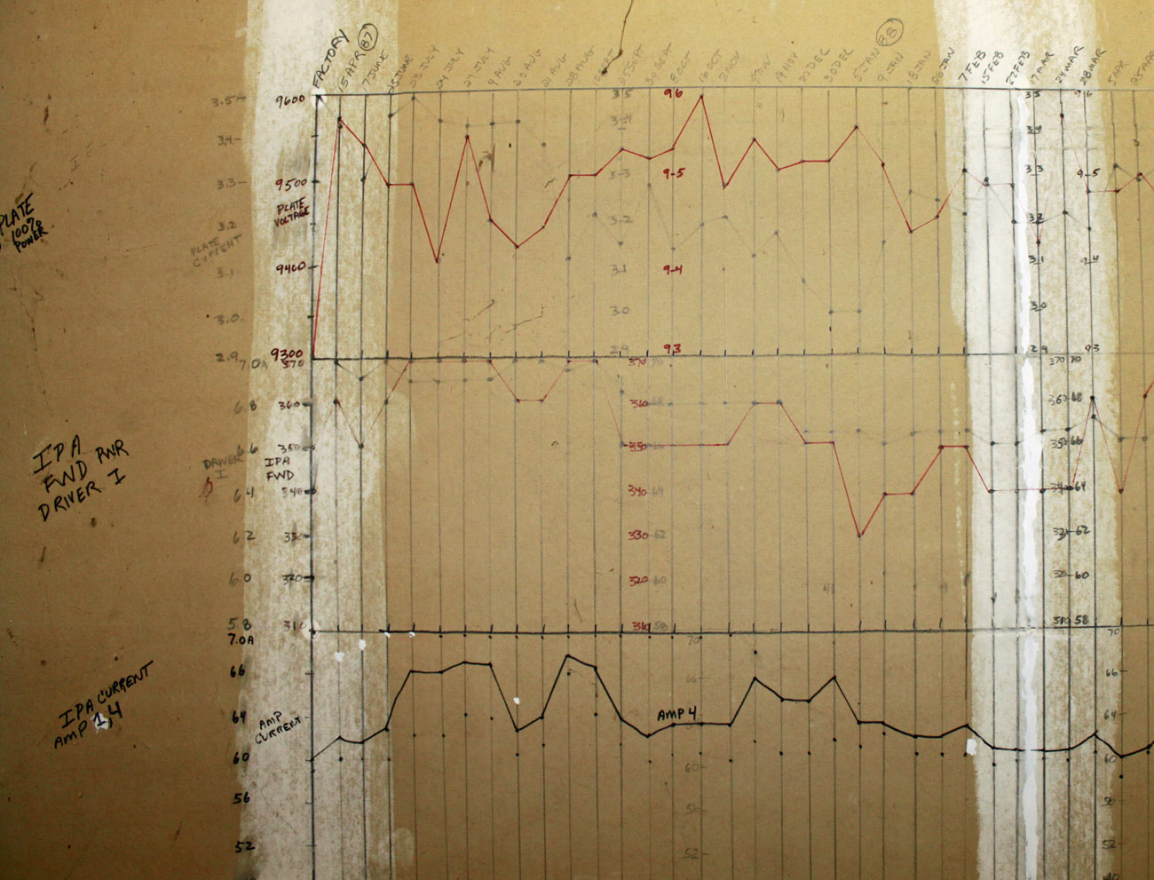
I saw this at the WIZN transmitter site in Charlotte, VT:
WIZN FM25K transmitter log
Somebody went through quite a bit of trouble to chart the transmitter readings from April of 1987 through about February of 1992.
A closer view:
WIZN transmitter log
I have not seen this at any other transmitter site, so I thought it was an interesting way to keep a transmitter log. It also seems to be time-consuming and a bit obsessive. Over the years, I have found my fellow broadcast engineers to be a somewhat strange group sometimes.
In the previous post, the issue with the WVOS-FM transmitter was detailed: The PA feed through/bypass capacitor had arced to the PA cavity causing lots of unwanted off-air time. When I went to order the replacement parts, of course, they were not available. It seems that Broadcast Electronics changed the design of its transmitters in the late 1980s to use a different feed-through arrangement.
They were nice enough to send us a nifty retrofit kit; BE part number 959-0272 which replaces BE part number 959-0115. If interested, the six pages of installation instructions are available here, for your reading pleasure.
The retrofitting itself was quite the job; drilling six mounting holes and one one-inch feed through hole in the PA cavity, mounting the new feed through housing, rewiring the high voltage connection to the tube and back to the HV bleeder assembly, etc. What with all of the drilling, sawing, filing, deburring, and whatnot, I began to wonder if the transmitter would ever run again. This is the transmitter before the modification:
Broadcast Electronics FM3.5A PA cavity
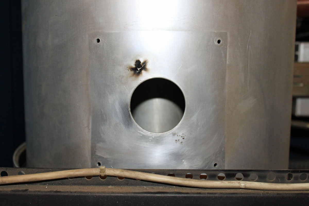
This is the old high voltage feed through hole, arc mark clearly evident.
Broadcast Electronics FM3.5A old high voltage feed though
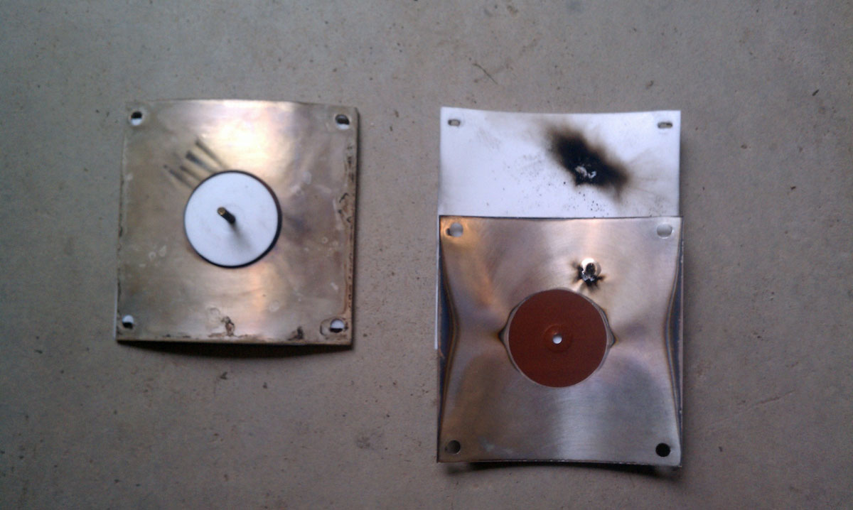
This is the modified feed through/bypass configuration.
Broadcast Electronics FM3.5A new PA feed through/bypass capacitor
While doing this work, I removed the tube and put a plastic sheet in the bottom of the PA cavity and around the HV parts at the bottom of the transmitter. Somehow, getting aluminum filings in the tube socket seemed like a bad idea. I also thoroughly vacuumed out the entire transmitter once all of the metal work was done.
I removed the Kapton capacitor plates from the old feed-through arrangement and reinstalled the Teflon insulating plates to keep the air flow out of the tube cavity going in the correct direction. The new capacitor looks very beefy, perhaps it will never fail again.
Once the installation work was done, I brought up the transmitter first with no screen and no connection to the tube anode. Then with the tube connected, and finally with the screen supply turned on. The tuning needed a brief touch up but all in all, the transmitter came up and ran well with the new feed-through arrangement.
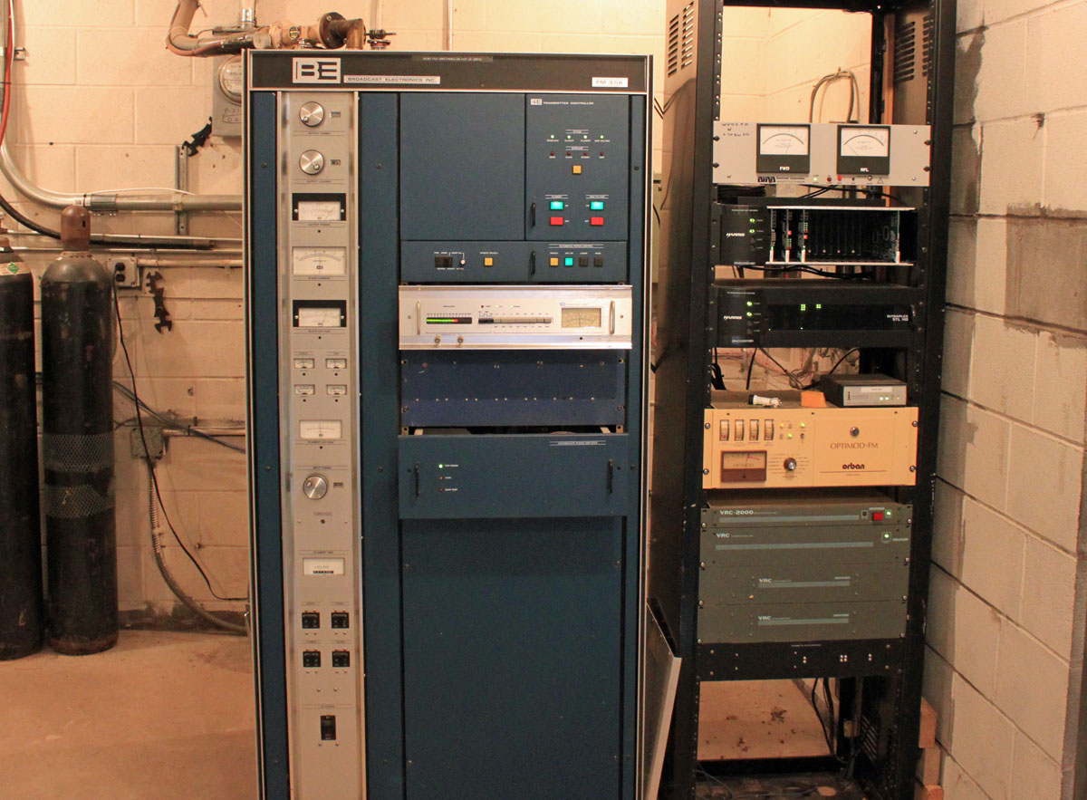
This Broadcast Electronics Fm 3.5A will be thirty years old in April. We should have a party!
Broadcast Electronics FM 3.5A, WVOS-FM, Liberty NY
Unfortunately, this transmitter is not doing too well these days. The PA high voltage feed through capacitor has arced over to the PA cavity, causing the station to be off the air.
BE FM3.5A HV feed thru capacitor
Naturally, this happened over the weekend, parts will not arrive until Tuesday at the earliest, and the station is without a backup transmitter.
Obviously, trouble shooting this was a two-person job. Never work alone on HV equipment. The symptom was the main circuit breaker was tripping after the HV on command. Starting from the transformer end of the HV power supply circuit and working toward the anode of the PA tube, all of the components were tested by isolating each component then turning the HV on. Special care was taken to discharge all components after each test. The capacitors and bleeder resistors were reconnected at the same time. There is too much risk involved with charged 8 KV capacitors and no way to bleed that charge to ground. Everything worked up until the PA cavity was reconnected (without the tube), then the breaker tripped again. Thus, the above feed-through capacitor was removed and disassembled, revealing the damage.
The question is, how long should transmitting equipment last? After all, if one were running a freight delivery company, you would not be driving around in thirty-year-old trucks, would you? No, not if you wanted to stay in business. Like all electro-mechanical equipment; transmitters, consoles, STLs, antennas, computers, etc wear out. A smart plan would be to have a replacement schedule and be putting money into a capital equipment replacement fund. Equipment life varies with the type. Getting twenty years out of a main transmitter is a pretty good service life, going beyond that is pressing one’s luck. Ten years on any one computer is a very long time. Then there are certain transmitter manufactures that drop support on older units, which makes it difficult to keep them operating. Owners and managers need to be cognizant of the age and condition of critical infrastructure. As field engineers, how much time do we devote to keeping antiquated equipment running, or should we even be servicing it at all? As independent contractors, we incur a liability whenever we touch something. Where does the ownership’s responsibility lay in providing safe, functional equipment for their stations? All interesting questions.