How effective are they at filling in or expanding coverage for FM stations? The answer is, it depends. Most have heard of the quadcast around New York City on 107.1 MHz formed in 1996-98. It was well documented in Radio World and several other publications as a clever way to overcome the suburban rimshot problem. Four signals on 107.1 were synchronized using GPS timing data, then fed the same program material. They were WYNY, Briarcliff Manor, NY; WWXY, Hampton Bays (Long Island), NY; WWYZ, Long Branch, NJ; and WWYY Belvidere, NJ. These being four separate Class A FM stations, the 60 dBu contours did not overlap. There was some mutual interference in some areas, but there were few if any reception negative zones where the signal strength is equal between stations.
In early 2003, I was a part of the disassembly of the quadcast. In the end, it is difficult to point to any one thing that leads to the breakup. The station’s owners, Big City Radio, had filed for bankruptcy. I am not sure if the company ever had the correct formula for marketing and sales, given the strong suburban, but weak and lacking building penetration in Manhattan signal. The station initially had a country format, something that armchair quarterbacks said would not work in New York City. After a few years, Big City changed the format to Rumba, a Spanish/Caribbean music format, which did worse than Country. The fact is, that it never lived up to expectations and the station was worth more separately than together. Given the right circumstances, it could have worked.
The other synchronized FM broadcasts are those where boosters are employed. These are a good deal more difficult to configure because the booster signal is within the main station’s 60 dBu contour. Often cases, where there is severe terrain shadowing or other limitations, a well-positioned booster that is in a population center can greatly improve the signal in those areas. This was formerly the duty of an FM translator, however, those stations seem to be taking on a life of their own, without regard for the intent of the current FCC rules. Boosters can also be called a single frequency repeaters or single frequency network (SFN).
The disadvantages of an SFN are the aforementioned negative reception areas. To the receiver, this will create a multipath or picket fencing situation, which is objectionable to most listeners. The advantages are, of course, better coverage in key areas, spectrum efficiency, and the ability to create a network of common frequency systems. Think of how easy it would be if all NPR stations were all on the same frequency, for example.
The key to making a booster work is to synchronize several aspects of the RF and Audio signals:
- RF carrier frequency
- Stereo pilot frequency and phase
- Audio amplitude and phase
The RF carrier frequency, stereo pilot frequency, and phase are locked with a GPS. Most transmitters have a 10 MHz or 1 PPS input for this.
The audio amplitude and phase synchronization are slightly more complicated. Basically, all of the audio should be coming from one audio processor and the path to the individual transmitter sites has to be very low latency. RF STLs work for this setup well, if there are suitable paths.
Once that is established, the audio timing is used to move the interference zone away from undesirable areas. There will always be an interference zone where both signals are received at the same relative strength causing dropouts.
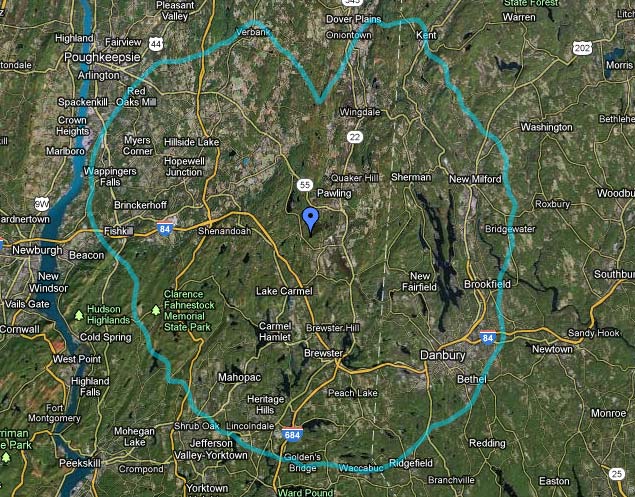
This is the situation with WDBY in Patterson, NY. The main transmitter site is located on a hill in Patterson and has a power level of 900 Watts at 610 feet (186 meters) HAAT. The main population area is Danbury, CT, to the southeast, about 12 miles away. Between the two, there are several imposing hills, which create reception issues in Danbury. Therefore, WDBY FM1 was placed in service at the Danbury Medical Center. The booster has a power output of 1,200 Watts, at 0 feet (0 meters) HAAT (49 meters AGL).
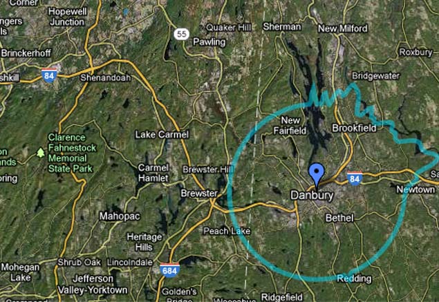
Therefore, the southern area of the 60 dBu contour is filled in by the booster. The interference zone between the two transmitters is determined by the amount of delay in the audio between the two units. If both are time the same, the interference will occur at precisely 1/2 the distance between the transmitter sites, which in this case is 10.18 KM from the booster. Looking at the population maps, it might be better to move that more toward the north, away from Danbury.
The formula for computing audio delay time is:
A-B=C where A is the distance between the transmitters and B is the distance to the interference zone from any given transmitter. The product of that is multiplied by a constant of 3.34 to obtain the time delay in microseconds. Therefore, if the interference zone is desired to be further outside of Danbury, say 15 KM away, then the equation looks like this:
20.358 kM -15.0 kM = 5.358 KM
5.358 KM x 3.34 = 17.89 μS delay from the main transmitter site will put the interference zone out in the middle of nowhere, away from Danbury. This is the total delay between the two stations, therefore any difference in STL paths needs to be included in this figure.
Nautel has a good webinar on SFNs which can be found on their website: Single Frequency Networks Webinar
Nautel equipment has most of these features built into it, therefore, the implementation of an SFN using Nautel exciters and transmitters should be relatively straightforward.

Nicely detailed, Paul. I remember back in the late 1980’s went I use to tend to things at the former WDJF-FM/WEBE-FM site in Wilton that WRKI had an STL hop located there to send a signal to an on-channel booster in Norwalk. I don’t know if they are still operating it presently but I remember being curious on how the two were synchronized to prevent or lessen the picket fencing effects.
Thanks, Bill. WRKI had boosters in Bridgeport and Norwalk. There was an STL from Brookfield to Norwalk that was always the weakest link. Those boosters also did not synchronize and time the audio signals, therefore there was issues with interference from the main signal.
With the newer gear, the concept works better, but it is still not perfect.
I haven’t got any experience about SFN.
Thanks Paul for your article, easy to understand SFN.
I remember with the 80’s WRKI setup that the signal was picked up off-air in Wilton and transmitted via microwave link. If my memory is correct, the off-air signal was received with an FM mod monitor and the baseband was fed into the STL directly. I remember an ancillary box, perhaps for phase synchronization of the carriers between the main and booster, but it was so many years ago it’s difficult to recall.
With GPS technology things are much cleaner to implement but I’m curious on how objectionable the “ring of fire”, that being the interference area between the main and booster, is to the listener in an automobile.
In the 90’s The WRKI set up was done with TFT reciters and STLs using the 62 MHz IF output from the reciter to feed the next STL transmitter in line. This replaced the off air receiver in wilton.
The system worked okay, the signal traveled from the Brookfield studio to the transmitter site, then was relayed to Wilton, then to Bridgeport. There was no attempt to lock the carrier frequencies, pilot phases or time the audio. Thus the signal interference fell where it may, with the propagation delays from the STL’s it was likely more toward the boosters than the main signal. Being that the boosters covered more populated areas, this was less than optimal.
Those licenses still exist, I’d bet that if the system were re-invigorated with today’s technology, it would work much better.
I’ve always wondered if this would work reliably on wideband FM. We’ve been doing this in two-way and paging for decades. Multi transmit simulcast is how most large public safety radio systems, both trunked and conventional, are accomplished. It works fairly well thanks to GPS. Wasn’t always the case back in the days of rubidium time bases…now digital modulation, well…CQPSK P25 plain sucks. But digital is always better!
Ah yes the WRKI reciters. I spent a few hours with Pat Carlone unboxing them and making up jumpers and the like. Do you remember the blaupunkt ARI system for traffic updates? Yep those were the days
@Erik, the key for broadcasters is to make the switch between transmitters as seamless as possible, since the listener will perceive any drop in signal, thus the need to synchronize everything. I can imagine that digital modulation schemes would be harder to do this with as the phasing errors would increase with distance from transmitter.
@Mark, No, I never worked at WRKI myself, so I would not remember that.