Alternative title: Who will really benefit from all digital AM HD Radio™?
Remember when, at license renewal time, radio and TV stations played this announcement:
On (date of the last renewal grant), (station’s call letters) was granted a license by the Federal Communications Commission to serve the public interest as a public trustee until (license expiration date)…
Emphasis mine.
There seems to be a disassociation between those words and the actions of certain broadcasters who view their licenses as a matter of fact and have little regard for the public interest. The FCC exacerbates the situation with the attitude that everything, including the entire radio frequency spectrum, is for sale to the highest bidder. John Anderson (DIY Media) has a great article on how big business interests game federal regulators into doing what they want. This happens in all sectors; banking, agriculture, energy, health care, media, military and so on. There are many examples of shoddy regulators and big business gone wild over the last ten years to fully prove this theory. If you don’t believe me, do a little research. There is no reason to think that the FCC is different from any other federal regulatory agency.
The vast majority of mass media outlets in the US are owned by just six major corporations (see below). Radio remains the only piece of the mass media system that has not been completely rolled up in consolidation. Currently, there is a small number corporate radio owners who own a combined ~2,300 stations and one public broadcasting network that accounts for another ~900 stations. I include public radio here because the majority of those station’s upgrades were footed by the taxpayer though grants from the Corporation for Public Broadcasting. That leaves a majority of the approximately 8,500 radio stations that are still owned by a diversified collection of medium and small groups and individuals.
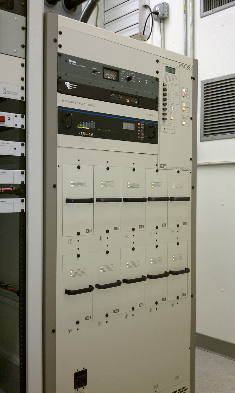
Forcing radio stations to adopt the proprietary, all digital HD Radio™ as the broadcasting standard would, in effect, drive many of those small owners and individuals out of business because of the exorbitant costs for equipment upgrades, antenna modifications, and licensing fees. This would create a new wave of consolidation as smaller groups and single station owners sold out. Any remaining small station owners will not have the legal wherewithal to fight against the coming waves of digital interference on both the AM (medium frequency) and FM (VHF) bands.
Therefore, the short answer to the question; who benefits from an all conversion to all digital HD Radio™ is iBquity and its investors, many of whom are found in the list of consolidated media corporations below. Who looses? Just about everyone else; small and medium group owners, independent radio owners, listeners, communities of license, radio employees, advertisers etc. For those sitting on the fence, thinking “I’ll just do my job any everything will be just fine.” Full implementation of HD Radio™ will destroy what is left of broadcasting in this country. Radio is already on shaky ground as a result of product dilution, staff cuts, mediocre programing and competing media systems. One more step backward, such as adopting a technically flawed digital system that works worse than its analog counterpart, and the remaining listeners may just say “screw this,” and abandon radio altogether. When the last radio station is turned off, what do you think will happen to your job then?
At the big NAB Las Vegas confab, FCC commissioner Ajit Pai and to a lesser extent, Commissioner Rosenworcel, encouraged people to write or email them with their ideas on how to revitalize AM radio. I suggest we take advantage of that invitation and tell them what HD Radio™ really is. There is a shrinking window of opportunity to join the discourse and be heard, now is the time.
Let not any one pacify his conscience by the delusion that he can do no harm if he takes no part, and forms no opinion. Bad men need nothing more to compass their ends, than that good men should look on and do nothing. ~John Stuart Mill
What is at stake? The future of diversified media and radio broadcasting in the US.
Sidebar: Mass Media Consolidation
Can the public trust a mass media that is owned mostly by six mega corporations to honestly and without bias report news, current events, investigate corruption, and be a government watch dog? History says no.
Who owns the media?
Time Warner
- Home Box Office (HBO)
- Time Inc.
- Turner Broadcasting System, Inc.
- Warner Bros. Entertainment Inc.
- CW Network (partial ownership)
- TMZ
- New Line Cinema
Time Warner Cable (spun off in 2009)- Cinemax
- Cartoon Network
- TBS
- TNT
- CNN
- HLN
- MapQuest
- Moviefone
- Castle Rock
- Sports Illustrated
- Fortune
- Marie Claire
- People Magazine
Walt Disney
- ABC Television Network (8 stations owned, 200 affiliates)
- Disney Publishing
- ESPN Inc.
- Disney Channel
- Radio Disney (31 stations, 2 affiliates)
- SOAPnet
- A&E
- Lifetime
- Buena Vista Home Entertainment
- Buena Vista Theatrical Productions
- Buena Vista Records
- Disney Records
- Hollywood Records
- Miramax Films
- Touchstone Pictures
- Walt Disney Pictures
- Pixar Animation Studios
- Buena Vista Games
- Hyperion Books
Viacom
- Paramount Pictures
- Paramount Home Entertainment
- Black Entertainment Television (BET)
- Comedy Central
- Country Music Television (CMT)
- Logo
- MTV
- MTV Canada
- MTV2
- Nick Magazine
- Nick at Nite
- Nick Jr.
- Nickelodeon
- Noggin
- Spike TV
- The Movie Channel
- TV Land
- VH1
News Corporation
- Dow Jones & Company, Inc.
- Fox Television Stations (25 stations)
- The New York Post
- Fox Searchlight Pictures
- Beliefnet
- Fox Business Network
- Fox Kids Europe
- Fox News Channel
- Fox News Radio
- Fox Sports Net
- Fox Television Network (175 affiliates)
- FX
- My Network TV
- MySpace
- News Limited News
- Phoenix InfoNews Channel
- Phoenix Movies Channel
- Sky PerfecTV
- Speed Channel
- STAR TV India
- STAR TV Taiwan
- STAR World
- Times Higher Education Supplement Magazine
- Times Literary Supplement Magazine
- Times of London
- 20th Century Fox Home Entertainment
- 20th Century Fox International
- 20th Century Fox Studios
- 20th Century Fox Television
- BSkyB
- DIRECTV
- The Wall Street Journal
- Fox Broadcasting Company
- Fox Interactive Media
- FOXTEL
- HarperCollins Publishers
- The National Geographic Channel
- National Rugby League
- News Interactive
- News Outdoor
- Radio Veronica
- ReganBooks
- Sky Italia
- Sky Radio Denmark
- Sky Radio Germany
- Sky Radio Netherlands
- STAR
- Zondervan
CBS Corporation
- CBS News
- CBS Sports
- CBS Television Network (16 stations owned, 200 affiliates)
- CNET
- Showtime
- TV.com
- CBS Radio Inc. (130 stations)
- CBS Consumer Products
- CBS Outdoor
- CW Network (50% ownership)
- Simon & Schuster (Pocket Books, Scribner)
NBC Universal
- Bravo
- CNBC
- NBC News
- MSNBC
- NBC Sports
- NBC Television Network (10 stations owned, 200 affiliates)
- Oxygen
- SciFi Magazine
- Syfy (Sci Fi Channel)
- Telemundo
- USA Network
- Weather Channel
- Focus Features
- NBC Universal Television Distribution
- NBC Universal Television Studio
- Paxson Communications (partial ownership)
- Trio
- Universal Parks & Resorts
- Universal Pictures
- Universal Studio Home Video
Large and medium group radio owners:
Bain Capital Partners, LLC Thomas H Lee Partners, LLC
- Clear Channel Outdoor
- Clear Channel Broadcasting (800 stations)
- Premier Radio Networks
- Radio Computer Services (RCS)
Cumulus Media (public)
- Cumulus Broadcasting (550 stations)
- Cumulus networks (formerly ABC Radio networks)
- Broadcast Software International
Townsquare Media (220 stations)
Entercom (109 stations)
Salem Communications (97 stations)
Saga Communications (88 stations)
Univision (69 radio, 42 television stations)
Radio one (69 stations)
Family Broadcasting (63 stations)
Beasley Broadcast Group (47 stations)
Moody Radio (36 stations)