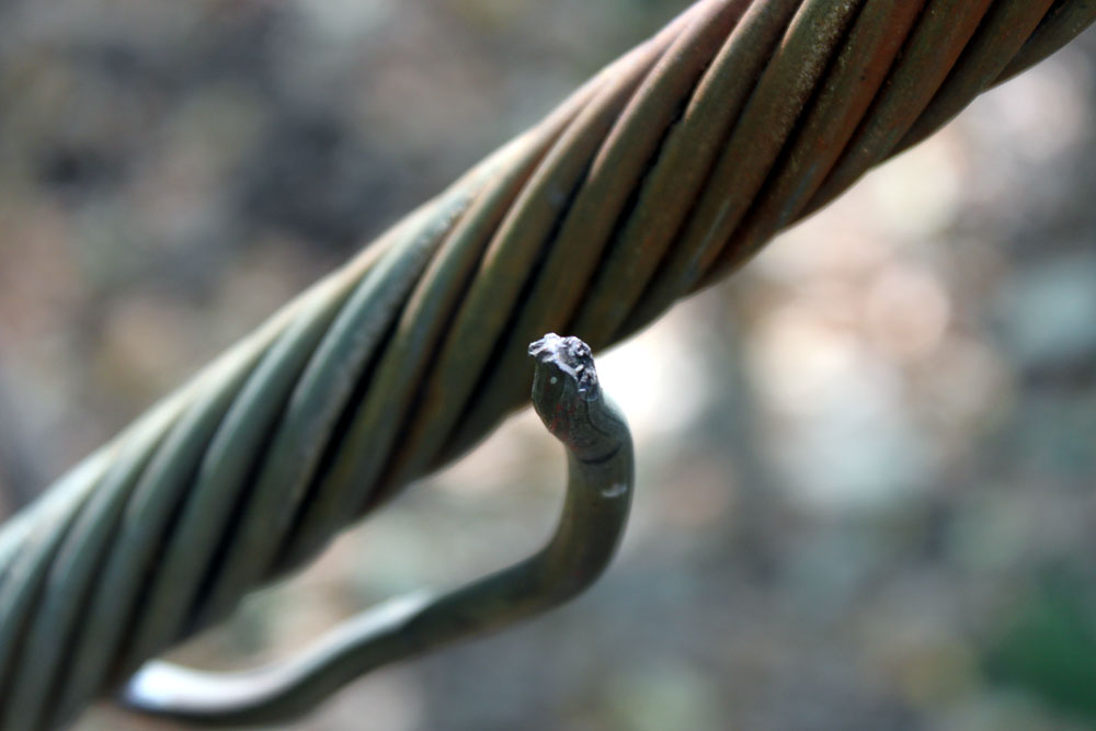
I found this on one of the guy wire anchor points for a 400-foot tower:
#2 solid copper wire burned open by a lightning strike
Had to be a pretty big hit to burn open a #2 wire. This is on one of six guy anchor points for the tower. The ground wire is U-bolted to each guy wire before the turnbuckle and then goes to ground. This was noted between the last guy wire and the ground rod.
It is important to find and fix these things, as the next lightning strike on this tower would have a less-than-ideal path to ground at the guy anchor points, forcing the current to flow through other parts of the transmitter site, possibly through the transmitter itself, to ground.
I generally try to do a brief inspection of towers, guy anchors, lighting, painting, and a general walk around the property twice a year. That helps prevent surprises like “Oh my goodness, the guy wires are rusting through,” or “Hey, did you know there is an illegal “hemp” farm on your property?” Well, no officer, I don’t know anything about that…
I figured if I have this problem, someone else probably has it too. We have a backup antenna on one of our towers. The station has a TPO of 28 KW, which is starting to get into the semi-serious level. This antenna is connected to Andrew 3-inch heliax that was installed in 1971. It has a spiral inner and outer conductor, which is no longer made by any manufacture of heliax.
We completely rebuilt the transmitter site a few years ago, moving a lot of things around. One part of the project was installing a coax port on the wall and moving all coaxial cables to that entrance. The main antenna is connected to Cablewave H50J coax. I ordered a new connector for that transmission line, no worries. When I cut the back up transmission line, I figured I could re-apply the old Andrew connector.
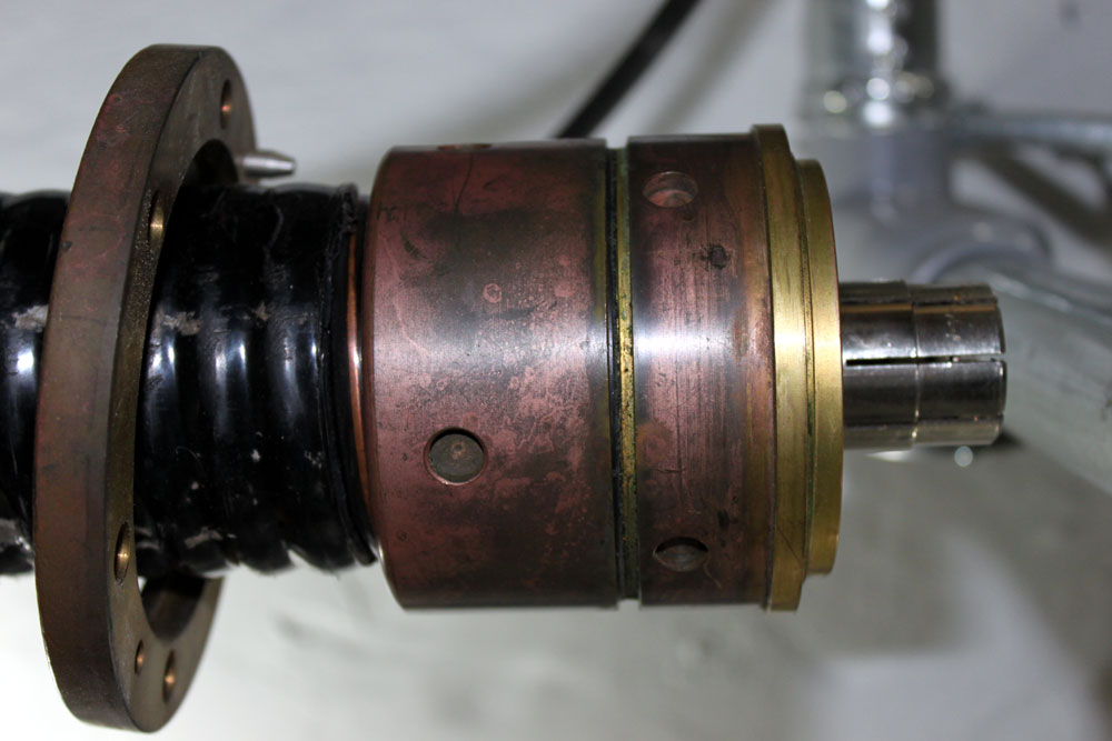
Andrew A909D type 78 AGM 3-inch coax connector
That is all fine, however, I removed the connector without reverse engineering it, that is to say, I didn’t pay close attention to how the inner and out conductors where cut, or how the jack was cut back. I will have to reverse-engineer the thing now.
Here are the steps I followed:
Check out the CommScope – Andrew website for documentation. A search shows they only have the current connector, which is nothing like this one and will not work with spiral conductors
Call Andrew and spend many minutes on hold or explaining to various helpers what I want. I was met with a universal “That is not an Andrew Part number,” or “Gee, I wish I could help but…”
Take the thing apart and begin measuring stuff with a ruler. Write everything down and draw out a diagram.
Trim off the excess cable then practice putting the thing together once.
Make the final cut and put the re-used connector back on the Andrew transmission line.
You can skip steps 1 and 2 since I already did them for you.
A few things to note:
The inner and outer conductors should be cut flush and as close to perpendicular as possible.
The inner conductor slug has a left-hand thread. This makes the slug tighten against the bushing.
The outer jacket is cut back about 2.5 inches
Place the EIA flange on the cable first, then thread the back nut onto the outer conductor, then thread the rubber gasket onto the outer conductor. The gasket is a tight fit, use petroleum jelly to lubricate it. This is a gas block connector, so special attention is needed with the gaskets.
The inner conductor has triangular pieces 1/8 inch deep cut around the diameter, the depth of the inner slug is critical to the connector going together correctly.
The inner conductor is folded inward over the end of the slug. Bushing, dielectric spacer, and EIA bullet are connected to the inner conductor slug and snugged down with a standard screwdriver
The outer conductor is nipped 1/8 of an inch around the diameter
The outer conductor is folded outward over the collect ring
Use some petroleum jelly on all the O rings
Carefully screw the connector together
Final tightening requires a special spanner wrench or attachments for a socket wrench. The tower crew had these in their shop.
If you have a spectrum analyzer, check its return loss and see what it looks like before slamming a full load on it. If not, turn things on and bring them up slowly. Feel the connector to make sure it is not getting warm. If there are problems, heat will be the first warning sign.
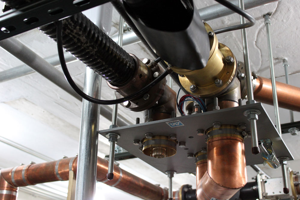
3 Inch coax patch panel
Once together, I ran the transmitters for a combined output of 10 KW and got about 50 watts return, which was much the same as it was before.
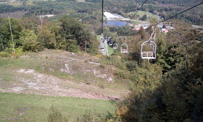
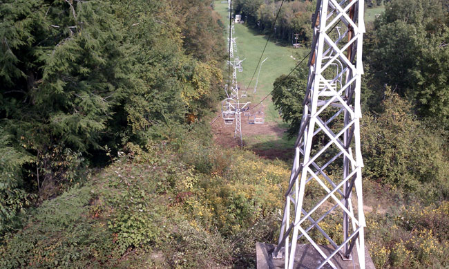
One thing that I like about the radio engineering job, every day is different from the last, at least when doing fieldwork. Access to transmitter sites can be a challenge, especially in the Winter months. Last Wednesday, I was doing work for WBEC in Pittsfield, MA. Their FM transmitter site is atop Mahanna Cobble in the Bousquet Ski Area. The summit is about 1,800 feet AMSL and since the terrible rains last month, not been accessible by vehicle. No worries though, somebody built this nice chair lift for us to use:
Bousquet Ski Area chair lift going downhill
Going down! I forgot to take pictures on the ride up.
Bousquet ski area chair lift
The steep part of the hill.
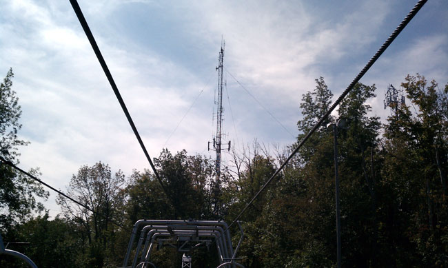
Top of the hill radio towerAmerican tower site top of Bousquet ski area
One of two towers, both owned and managed by American Tower Corporation. This is the older tower that has the radio station, somebody’s translator, some paging and two-way stuff, and sprint PCS. The other tower is to the right, out of the picture and holds cell carriers.
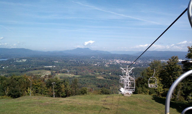
View to the north over the valley, WBEC-AM’s two tower directional array can be seen in the lower left hand side of the picture.
View to the north
WBEC-FM’s transmitter, it’s in there somewhere:
WBEC Nautel VS 2.5 transmitter
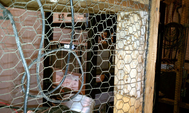
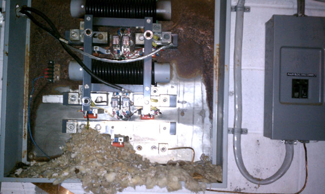
Polyphasor surge protector has seen better days. It suffered some serious damage and was removed from the circuit. Now, it makes a convenient home for rodents. Reduce, reuse, recycle:
Polyphasor surge suppressor
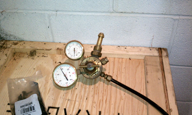
Something is missing…
N2 regulator with nothing to do
Now where did I put that Nitrogen tank? The site needs a little work and that’s okay, we came to work and get paid.
It was a hot day, it was a cold day. The tube transmitter was running, the solid-state (HD-1) transmitter was off the air. The books show that the company has deep pockets, but the accountant has short arms. And so it goes. In a sordid, yet familiar tale of leaping three-quarters of the way across a river, the builders of this transmitter site seemed to think of everything except the cooling requirements for a 35 KW FM transmitter.
Instead of installing real commercial AC units, someone decided that 34,000 BTU window units were the way to go. At one time, there were eight of those units, all single phase 240 volts sucking down gobs of power and freezing up when the outside temperature dropped below 40°F. This was always a problem but became more so when we took over the maintenance of this site. When there was a full-time engineer, his time, apparently, could be wasted running back and forth turning the window units on or off in the winter as required. Now that a contract company is doing the work, it becomes cost prohibitive to require such things.
Therefore, the time had come to make a change. To that end, six of the 34,000 BTU window units were removed from the building. Two of the existing holes in the wall were used to create an emergency cooling system, consisting of a 4,292 CFM fan and a couple of shutters. Two other holes were used for the new air conditioners and two holes were blocked up. The remaining two window units were left in place in the combiner room, which is a separate cooling zone.
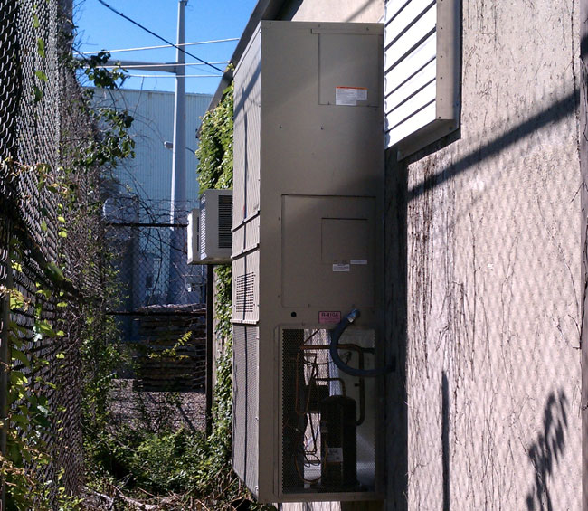
Bard 5-ton wall mount AC unit and cooling fan shutter
The new ACs are five-ton wall-mount Bard units. These are three phase and should be more than enough to keep the transmitters cool. Here is how I arrived at that conclusion:
The entire building load when the main transmitter is running at full power, without the transmitter room air conditioning, is 60 KW.
All of the building loads except the transmitters go through a single-phase panel.
The load on the single phase panel is 10 KW, thus the transmitter load is 50 KW (this 10 KW is mostly the single phase AC units in the combiner room)
The TPO is 32 KW, therefore the transmitter is generating 18 KW of waste heat.
One watt-hour = 3.412 BTU of energy, thus
18,000-watt-hours equals 61,416 BTUs
One ton = 12,000 BTU, thus
61,416 BTU ÷ 12,000 BTU = 5.118 tons
That will take care of the main transmitter waste heat. The HD transmitter generates another 4,000 watts of waste heat or 1.37 tons. The combiner is in another room and doesn’t factor into the calculation. The rest of the equipment is inconsequential, adding up to less than 100 watts.
The solar gain is more difficult to calculate, as it is based on the building structure, the type of construction, and the heat gain (loss) through the walls and doors. This building is concrete block, insulated, and has no windows. It is unshaded, however, it is painted a light color. All in all, the solar gain should be less than two tons on a hot day. Therefore the total AC load should be 8.25 tons or less.
Bard 5 ton wall mount AC unit
All that is left now was to install the things. Just pull up the truck and use a crane to lift them in place, except, no; that plan won’t work. This is the transmitter site at the power plant and the 138 KV lines overhead precluded any lifting with a crane. We instead had to build ramps and move things around on large-hand trucks. One unit is installed on the rear of the building, the other on the front. It required several days to make the ramps and four people to muscle the things into place.
The bottom air intake holes needed to be cut out for the new units. Cutting into the concrete block while the BE FM 35A was running proved to be another challenge. We used several sheets of plastic, shop vacs, and extra air filters on the transmitters to keep the concrete dust out of the PA cavities and motor bearings.
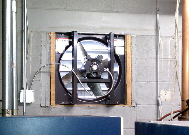
Plan B cooling consists of a 4,292 CFM Venturi fan mounted on the rear wall of the building. The fan is controlled by a ceiling-mounted thermostat set to 95 degrees. If the AC’s fail, the ceiling temperature will rise and the fan will turn on.
Transmitter site emergency cooling fan
The room volume is about 3600 cubic feet, therefore this fan will change the room air about once every 60 seconds or so. It is not the best plan to move humid, potentially dirty outside air through a building, but it it keeps the station on the air while the main AC units are being repaired, then so be it.
The entire system went on line last week and is working well.