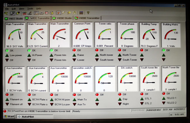
The old version of the software, that is. I like the graphical interface, just one glance is all that is needed:
Burk auto pilot
I have not had a chance to fool around with the newer version, the screen shots on the Burk website look a little bit different.
The setup and programming of macros is pretty easy; power/pattern change times, Pre-sunrise, and post-sunset functions, automatic tower light monitoring, AM Directional Antenna readings, and automatic transmitter restoration routines. If programmed correctly, the software can eliminate many of those late-night/early-morning phone calls, which is always a good goal.
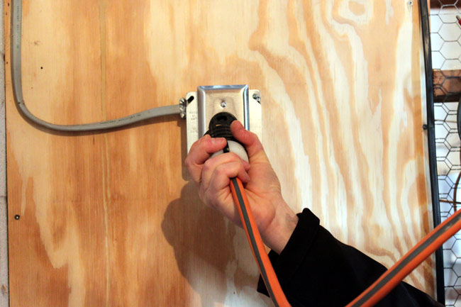
Sometimes there is just no way around it, especially with some modern equipment:
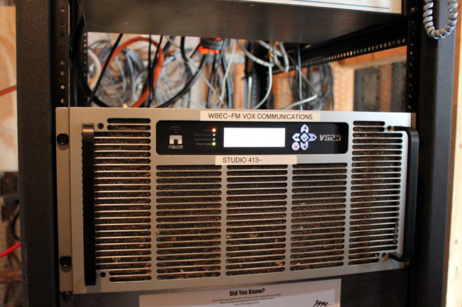
Hard restart, Nautel VS2500 transmitter
This Nautel VS2500 transmitter got all cranky after lightning struck the tower (or nearby) on Friday night. Thunderstorms in February are not unheard of, but they are unusual, at least in the Northeastern United States.
Nautel VS2500 FM transmitter, WBEC-FM, Pittsfield, MA
Anyway, the transmitter would not reset or restart via remote control, therefore, we had to ride the chair lift to the top of the hill and pull the plug to reset its logic and start over again.
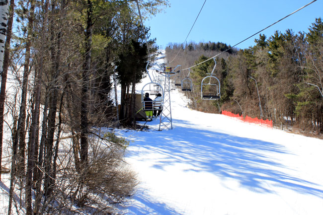
Bousquet Ski Area Chair lift
At least the trip up to the transmitter site was scenic. We had to wait a day for the winds to calm down, but all in all, not a terrible day. Did I mention the scenery?
I have worked in hundreds of transmitter sites over the years; AM, FM, TV, HF, Two way, Paging, Cellular, etc. So many, I have lost count. The one thing that is always annoying is equipment that is suspended from the ceiling at just the wrong height, AKA: The Head Smasher. It does not matter if warning signs are posted, I’ve seen them marked with black and yellow caution tape, and so on. If it is installed low enough for somebody to hit their head, contusions will result.
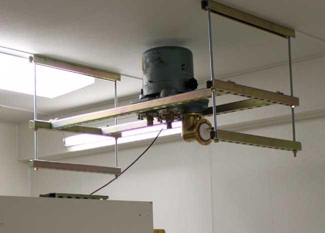
3 1/8 inch motorized coax switch mounted
Thus, when it came to installing this motorized 3 1/8-inch coax switch, there was only one way to do it. Installing it the other way would result in a head smasher behind the backup transmitter because the ceilings are low. The problem with this style of mounting is how to get to the motor and clutch assembly for servicing. There is but one inch of clearance between the top of the coax switch and the transmitter room’s ceiling. If servicing is needed, the entire switch would need to be removed, resulting in lots of extra work and off-air time.
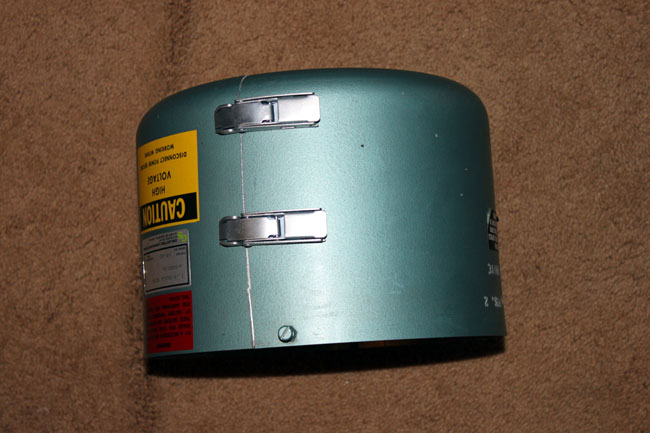
3 1/8 inch motorized coax switch cover
So, an idea was formed. Why not cut the switch cover in half and put some hinges on it. The cover itself is made of aluminum. I was able to carefully mark it out and cut it with a jig saw. Then, I attached a set of hinges on the back side and a set of latches on the front. It now opens like a clam shell.
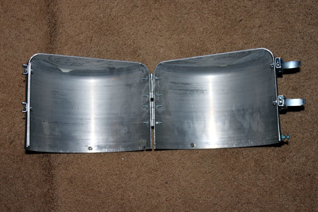
3 1/8 inch coax switch cover modification
Now, when access is needed to either the motor or clutch, the cover can be opened up and removed. Unless the actual RF contact fingers burn out, there should be no need physically remove the switch for servicing.
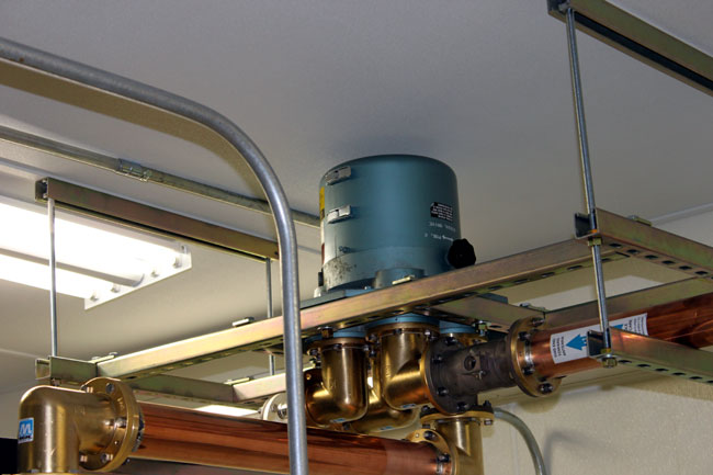
3 1/8 inch coax switch cover, modified
Cover replaced. This will not have to be removed very often, in fact, I have known some coax switches that never need service. Still, having the ability to quickly get the cover off and do some basic repairs is a good thing.
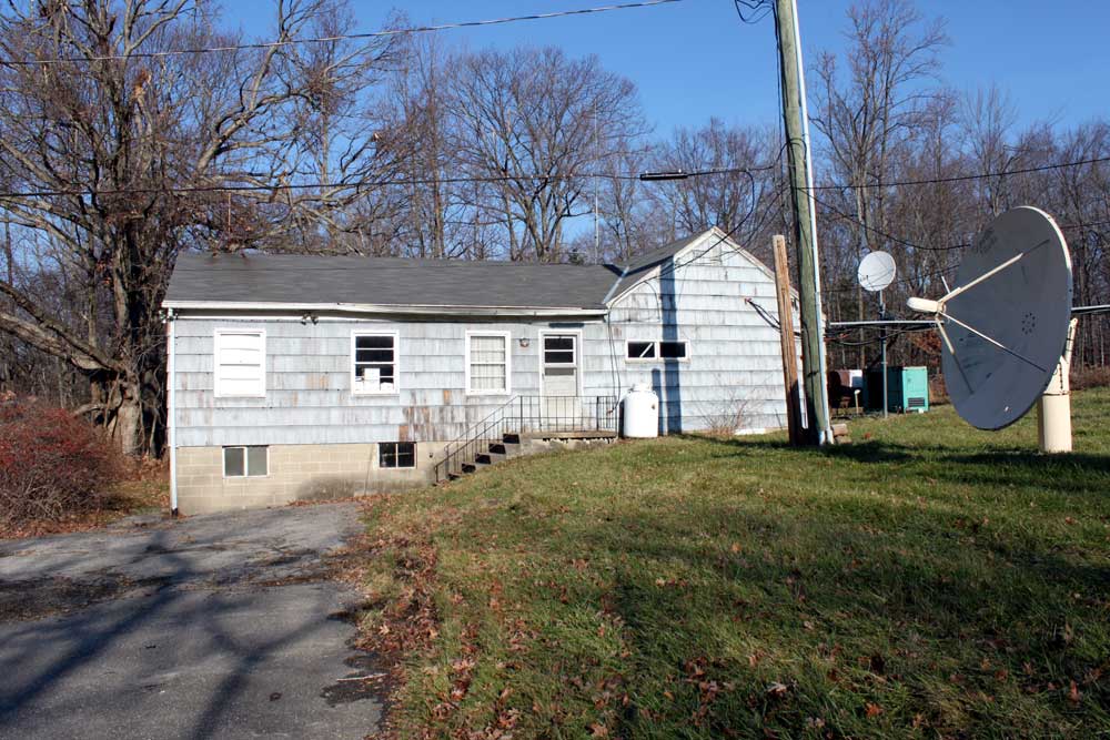
Blogging has been light due to workload being heavy, at the moment. We are engaged in moving transmitters out of this old house:
WINE 940 WRKI 95.1 former studio and transmitter site
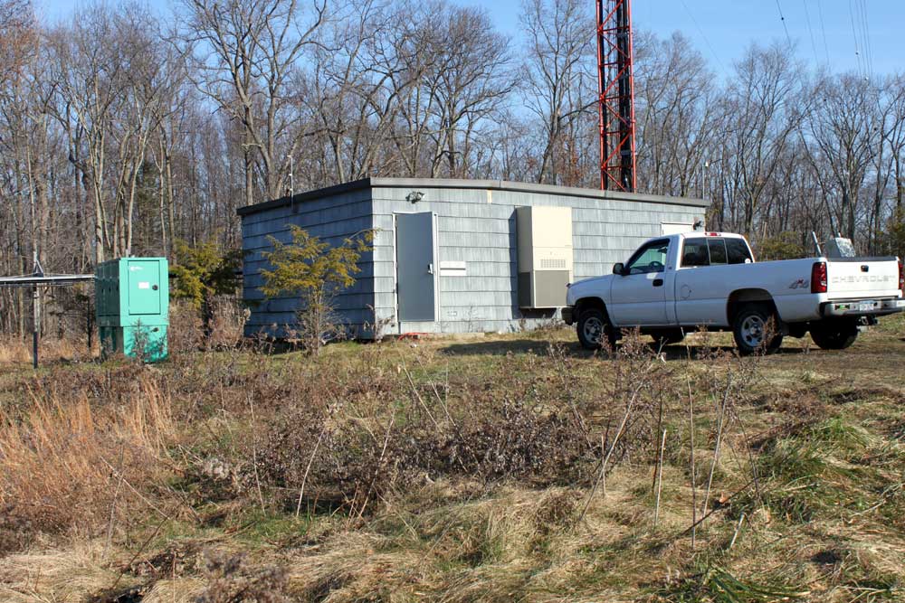
Into this new transmitter building:
WINE WRKI transmitter building at base of tower
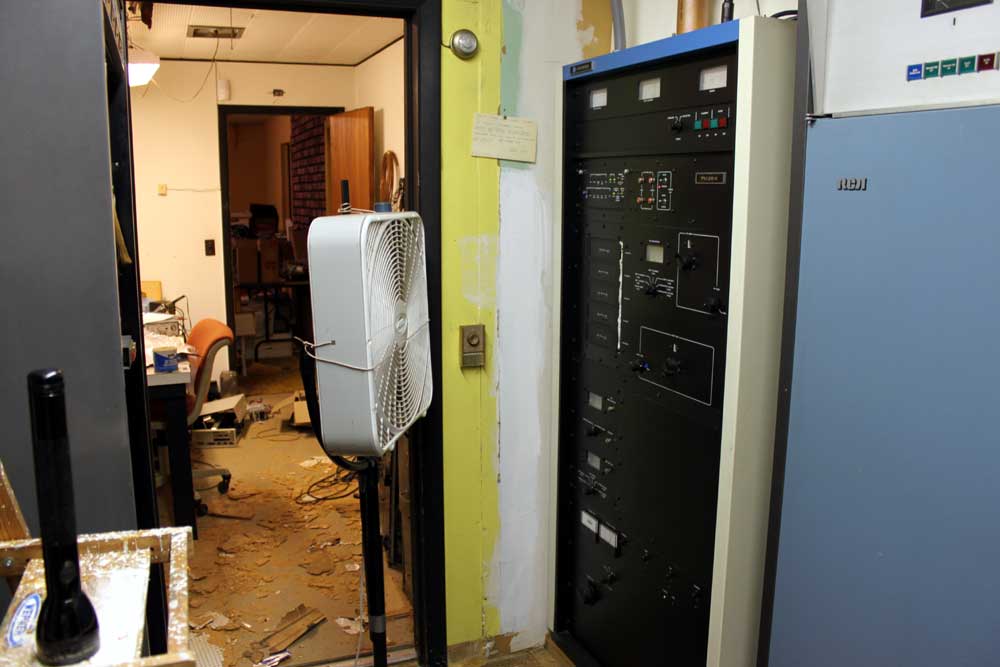
The former building was the original studio for WRKI, 95.1 MHz, which signed on in 1957. The co-located AM station, WINE 940 KHz, did not sign on until 1963. As such, the building is a little worn around the edges, so to speak. The FM transmitter has an auxiliary cooling device, for those hot summer days as the building itself is un-airconditioned:
WRKI Harris FM25K transmitter, circa 1986
The rest of the building is in similar condition. Ceiling tiles are falling off the ceiling and getting ground into the floor, junk is piled up in almost every corner, rodent feces, and the basement, don’t even get me started on the basement.
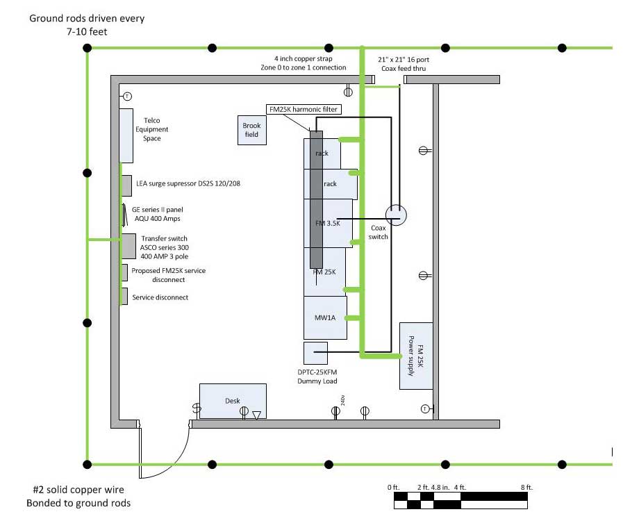
The basic floor plan for the new building is simple:
WRKI WINE transmitter room floor plan
Right now, the preliminaries are being done, mounting the coax switch, running conduit, pulling wires, etc.
A few design notes:
This building is much closer to the tower, which is sited on a high hill (715 feet, 218 Meters) and sticks up 500 feet (152.1 Meters) above that. Basically it is the area lightning rod, thus special attention will need to be paid to grounding and bonding. I decided to isolate the electrical ground in favor of the RF ground for lightning protection. This involves putting toroids on the electrical ground conductors.
The building itself is shielded with continuous steel plating, but that has been cut in a few areas to install air conditioners. Those areas will have to be repaired and the AC units bonded to the steel plate.
Back up cooling will be in the form of a large exhaust fan and intake louver.
The tower itself is AM radiator for WINE. It is 170 degrees tall, which means high RF fields at the base, therefore good RF bypassing is needed.
The transmitter room itself is fairly small for what needs to go in there. careful design and placement is required.
Here are some in-progress pictures:
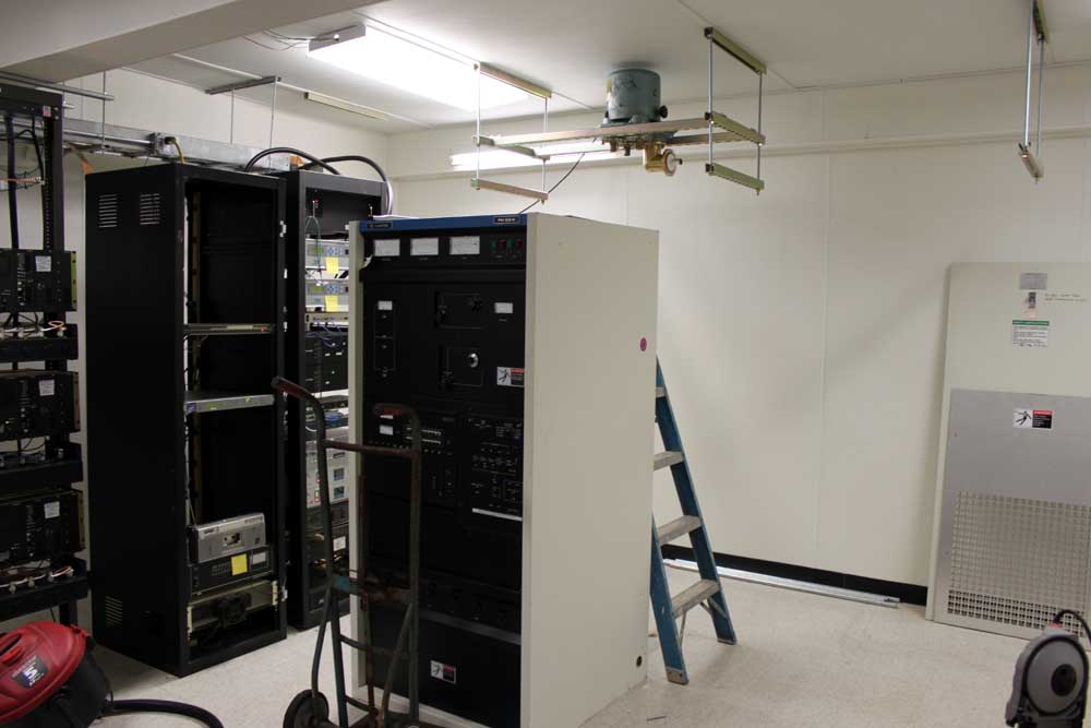
WRKI backup transmitter, Harris FM3.5K, coax switch in the background
The first order of business was retuning a Harris FM3.5K transmitter to function as the backup. The current backup transmitter is an RCA FM20E, which no longer runs. After the move is completed, that transmitter will likely be scrapped.
I attached super strut to the ceiling at four foot intervals. I used this strut to support the 4 port coax switch. All coax in the transmitter room is 3 1/8 inch hardline, which has a power rating of 40 KW. Since the transmitter power output is 20 KW, this leaves a lot of head room for problems. When working with a 3 1/8 inch coax, it is important to remember to cut the inner conductor 1 1/2 to 1 3/4 inches sorter than the outer conductor, otherwise the stuff doesn’t go together right.
The 30 KW air cooled dummy load was moved up from the other building and connected to the coax switch. This allowed the backup transmitter to be tested.
WRKI backup transmitter and dummy load
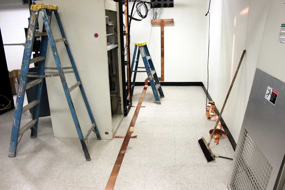
Three inch ground strap connects all the transmitters, racks, and dummy load to the station ground.
WRKI ground strap, new transmitter building
Electrical requirements are being met by a 400 Amp service backed up by a 120 KW generator. Once the conduit work is finished and all the wires pulled, the coax to the old building can be cut and brought into the new building, then the station can go on the air with the “new” backup transmitter.