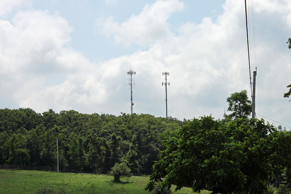
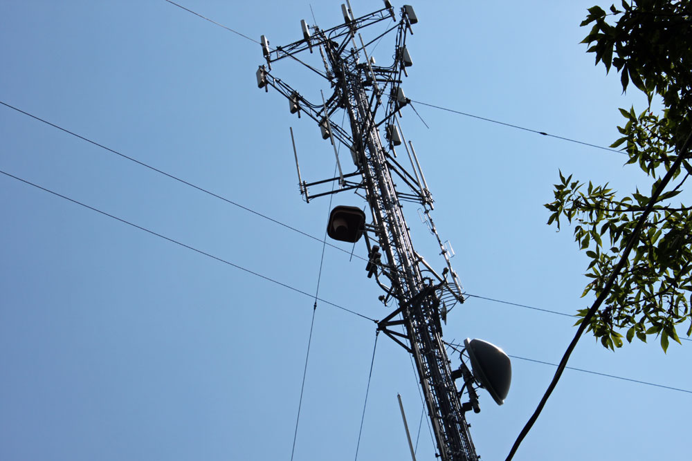
The WKZE single-bay antenna is mounted on the left-hand tower.
WKZE single bay Shively 6810 antenna with Radome
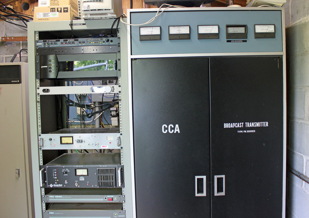
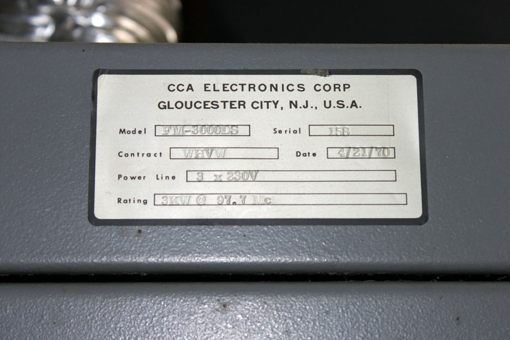
The transmitter is a CCA FM3000DS, made new in April, 1970:
WKZE 98.1 MHz CCA FM3000DS transmitter
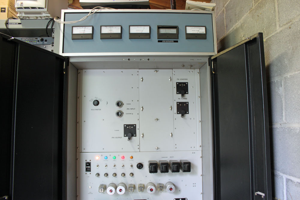
The CCA designs are dirt simple. Grounded grid, driven with an external solid state amplifier that is a modification.
WKZE CCA FM3000DS transmitter, 42 years onWKZE CCA transmitter name plate
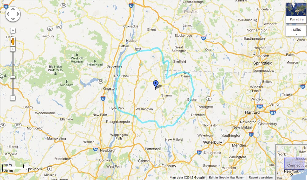
As you can see, this transmitter was originally manufactured for WHVW-FM, which is now WCZX. The station has a large, mostly cult following throughout the mid Hudson valley. Even though it is a 3,000-watt class A station, its coverage carries far beyond its theoretical 60 dBu contour:
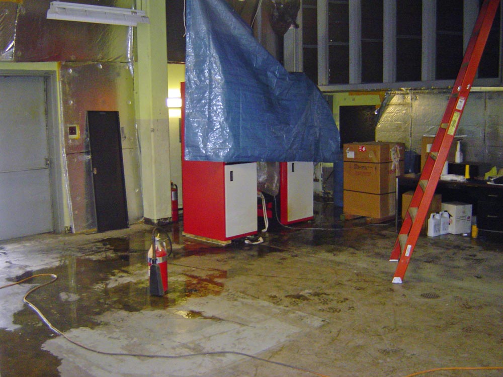
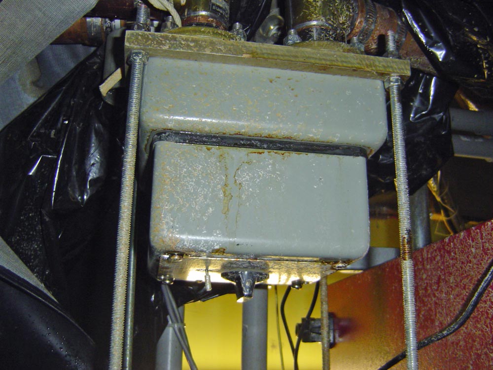
This incident happened a few years ago. I thought I had lost the pictures of the disaster, but I found them this morning on my thumb drive. Hooray! This occurred one morning just before Christmas after the area received a snow/ice/rain storm. The gutters on the old ATT long lines building were clogged with ice and the water on the roof built up. Unfortunately, the transmitter was installed directly below a disused exhaust stack for the former backup generators.
I received the off-air call from the morning show while I was driving to the office. I diverted and went to the transmitter site and found water pouring into the top of the main transmitter.
WBPM transmitter room flood
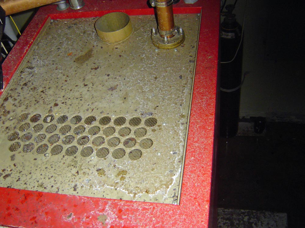
Thus, water ran down directly into the top of the QEI FMQ-3500 transmitter (transmitter was upgraded to 6 KW). Unfortunately, high voltage and dirty stack water do not mix. The combination of sooty, iron-laden water, and the B+ damaged much of the transmitter circuits beyond repair. The main transmitter is on the right, the backup transmitter is on the left.
I inspected the backup transmitter, also a QEI FMQ-3500, and it seemed to me that no water made it into the unit. I rigged the tarp to ensure that none did, which was a very pleasing bit of work, what with the cold, smelly, dirty diesel water dripping on my head and running down my neck and back.
Top of WBPM QEI FMQ-3500 transmitter
The 1 5/8 coax switch was also damaged:
WBPM 1 5/8 coax switch
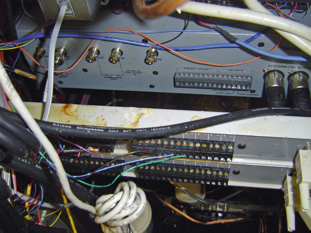
As was the remote control in the equipment rack:
WBPM Gentner remote control
Fortunately, the backup transmitter ran, although I pressed the plate-on button with a dry wooden stick while standing on a dry, non-conducting ladder. Even so, I still felt a little trepidation holding that stick.
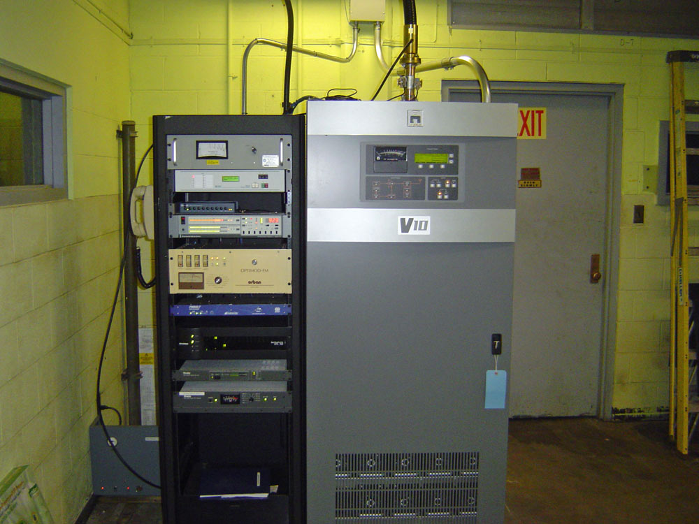
WBPM Saugerties, NY Nautel V-7.5 transmitter
It took almost a year, but finally, the insurance company for the building owner came through, and a new Nautel V-7.5 transmitter was installed. I believe this is the last V transmitter Nautel made. We moved the transmitter location across the room, not under the old generator stacks. We also removed the generator stacks and patched up the roof with hydraulic cement and roofing tar. By the way, that yellow color should look familiar to anyone who ever worked inside a Bell Telephone System building.
One of the issues that I have seen at many transmitter sites is inadequate cooling. Time was, when mostly tube transmitters were in use, a simple fan connected to a thermostat was all that was used to cool most transmitter sites. Even then, however, that setup was lacking for several reasons.
Those reasons are:
The amount of cooling provided was limited by the amount of heat in the outside air. On cool winter days, this is not a problem, but on hot, sticky summer days it could be.
No removal of humidity from the transmitter room was possible. This often leads to excess oxidation, corrosion of metal parts, and so on.
No matter how much filtering was used, bugs, dirt, and other debris were sucked into the fan, making transmitter room cleaning a chore.
With solid-state transmitters, air conditioning is required. Solid-state transmitter devices are far less rugged than tubes when it comes to heat. In a high-heat situation, a tube transmitter will keep running until its control circuits malfunction, or it catches on fire. A solid-state transmitter will crash long before either of those things happen.
Air conditioners should be adequately sized for the heat load plus a little extra. That information can be found in a previous post: A tale of two air conditioners.
As we all know, equipment malfunctions. When an air conditioning system goes bad at a transmitter site, things start to happen fast if there is no backup. That is when a backup cooling fan can save the day. A good rule of thumb for sizing a cooling fan is to exchange the total volume of the transmitter room every two minutes accounting for resistance from louvers and intake openings.
3200 CFM cooling fan, WHUD transmitter site
This fan is connected to a 120-volt contact on a thermostat attached to the ceiling of the transmitter room. The thermostat is set to 90 degrees, which gives a good bit of headroom for the air conditioners to maintain the room temperature while turning the fan on before the room gets too hot. It is also important to monitor the room temperature via remote control. Having an alarm contact connected to the fan thermostat is also a good idea.
There is no such thing as too much backup. Installing a louvered cooling fan affords a little bit of extra insurance.
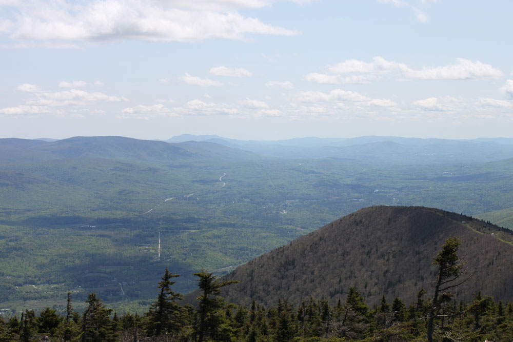
The transmitter for Vermont Public Radio, WVTQ 95.1Sudbury is located on Mount Equinox, near Manchester Vermont. Mount Equinox is one of the better mountain top transmitter sites to get to as it has a good access road, no jeep trails through the woods or ski lifts, etc. The Summit is 3,580 feet (1,175 m), which is the third-highest peak in the green mountains. On a nice day, the view from the top is spectacular:
South view, Mount Equinox, Vermont
The southern view with US Route 7 cutting through the valley below.
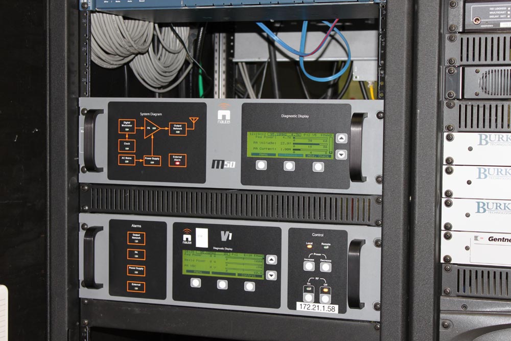
WVTQ is a part of VPR’s classical music network. They had a Nautel VS-1000 that had developed issues with the directional coupler. This unit was repaired and re-installed:
WVTQ Nautel VS-1000 transmitter, Mount Equinox, Vermont
The transmitter has a 7/8 EIA flange on the back, which had an elbow, then an adapter to a type N connector all unsupported. My boss felt that perhaps that perhaps too much weight on the EIA flange caused the crack in the directional coupler.
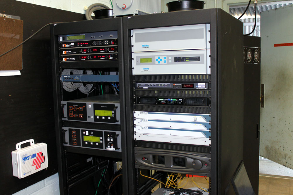
WVTQ transmitter racks and STL equipment
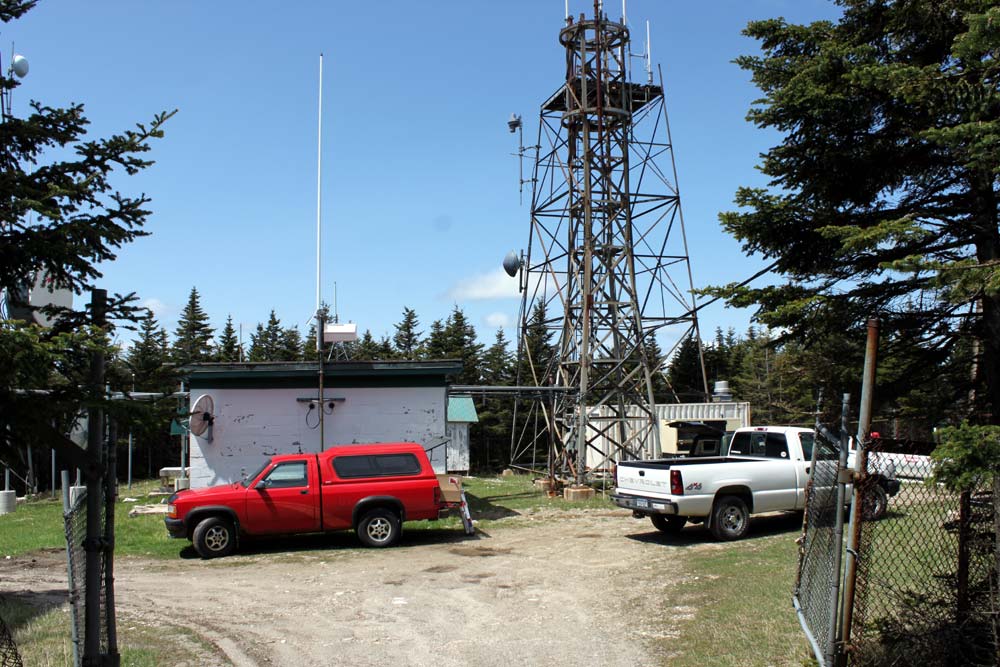
The transmitter site used to be in the basement of the hotel, but as that building no longer exists, it was moved over to the former RADAR site. The RADAR site consists of four 80-foot towers arranged in a square around a building. These towers now support two-way radio equipment and the like
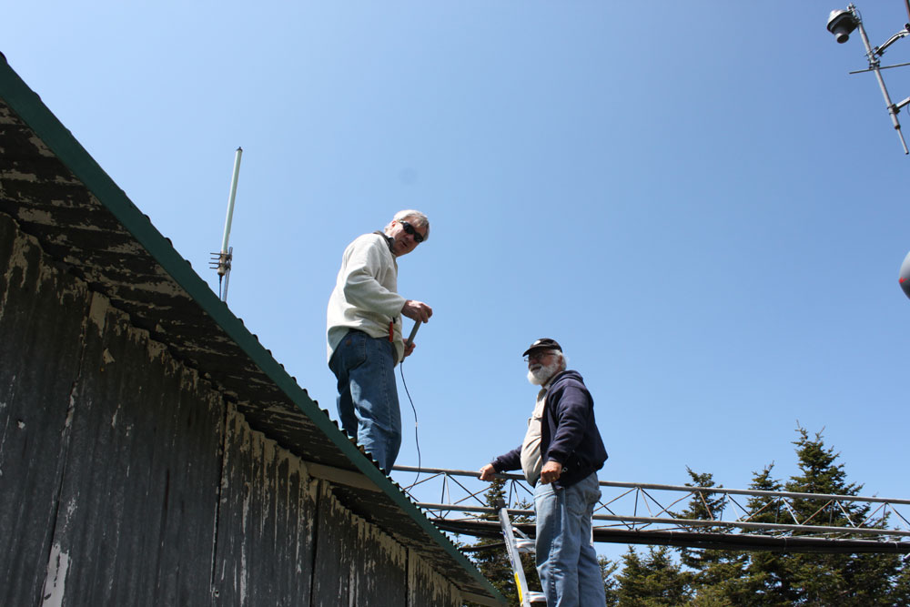
WVTQ transmitter site, Mount Equinox, VermontFiner points of GPS antennas
Your author (left) with Rich Parker of VPR discussing the finer points of GPS antennas.
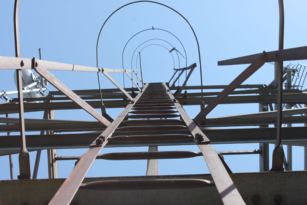
Stairway to heaven
Ladder to the top of one of the towers.
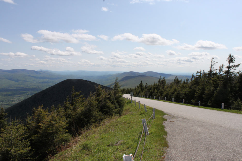
Hang Glider’s view, east side pulloff, Mount Equinox, Vermont
View from the turn-off on the east side of Skyline Drive. Known as “hang glider’s view” with good reason. This is on the saddle that connects little Equinox with big Equinox.
On a nice day, such as yesterday, it is very pleasant. When the road is covered in ice and snow, not so much.