Lightning season

Here in the northeast, there are seasonal variations in the types of weather phenomena encountered.  Blizzards in the winter, severe thunderstorms, and the occasional tornado in the summer, at least that is the way it normally happens.  This year, we have already had two thunderstorms and a stretch of unusually warm weather.  My highly advanced personal weather prognostication technique consists of looking at trends, and the trend thus far this year is warmer with more storms.

Weather Radar, thunderstorm line

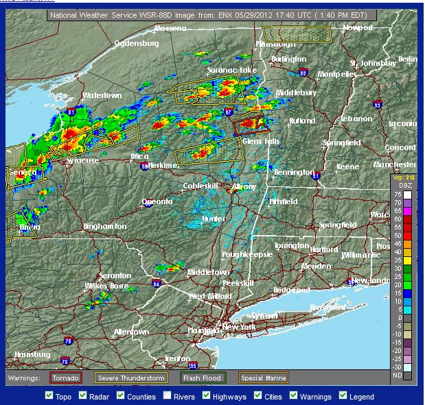
When the weather RADAR looks like this, it is too late.

To that end, it is time to go around and check all of the grounding and lightning suppression methods at various transmitter sites and studios.  I would rather spend a few minutes extra now than get called out in the middle of the night for an off-air emergency related to a lightning strike.

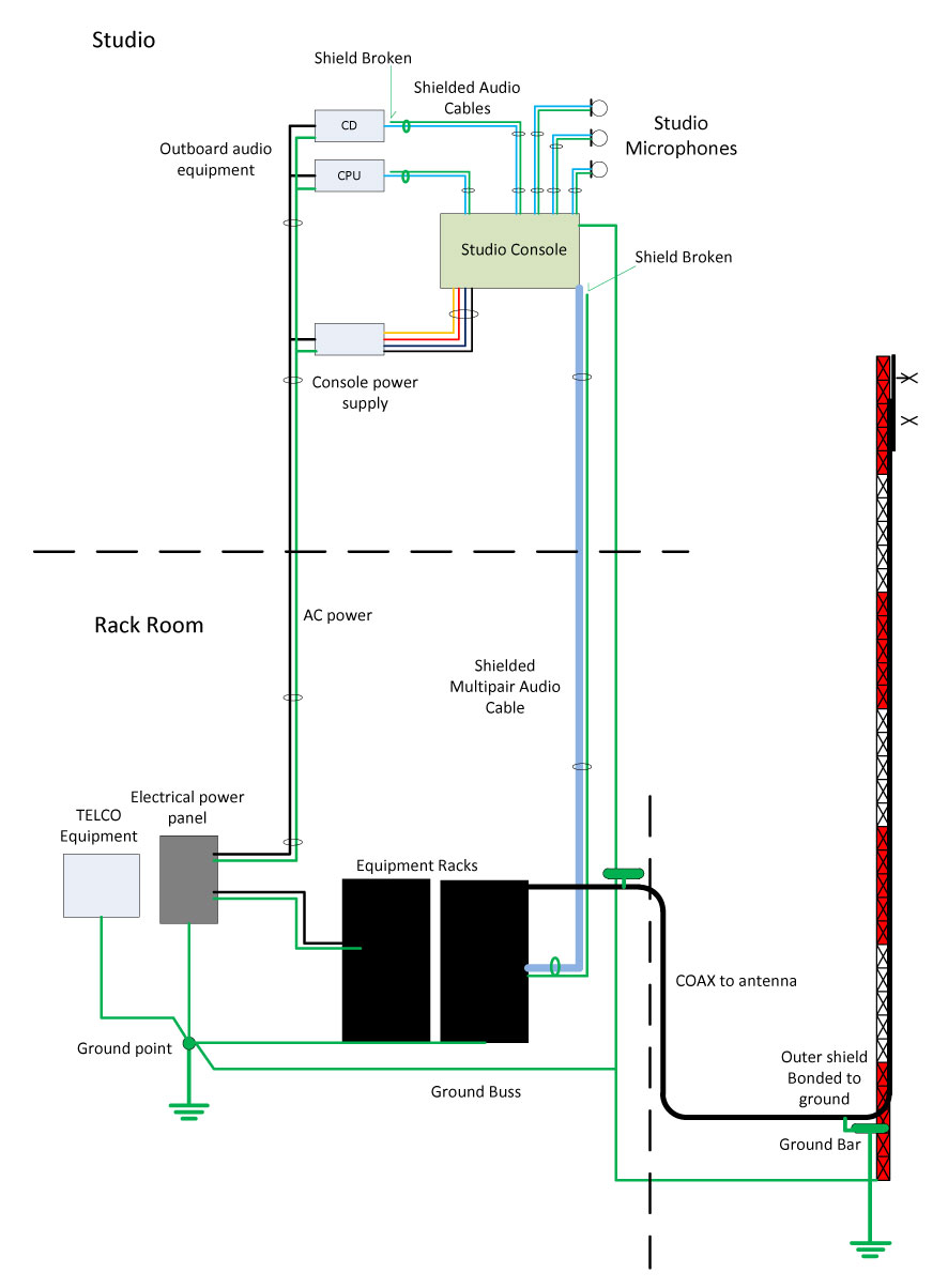
Proper grounding of all equipment, RF cables, and electrical service entrances is the minimum standard for transmitter sites.  Proper grounding means a common point grounding system connected to one ground potential.

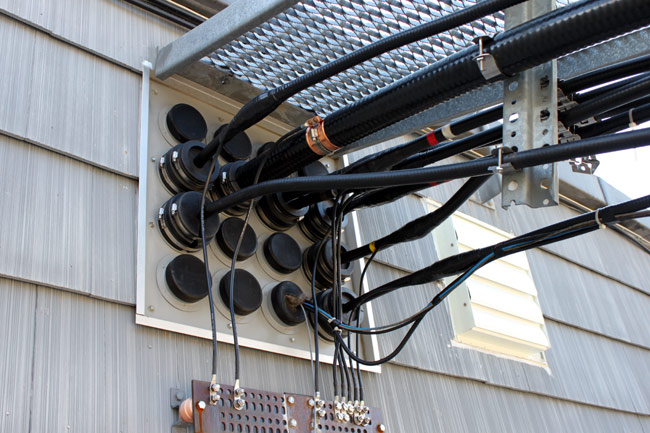
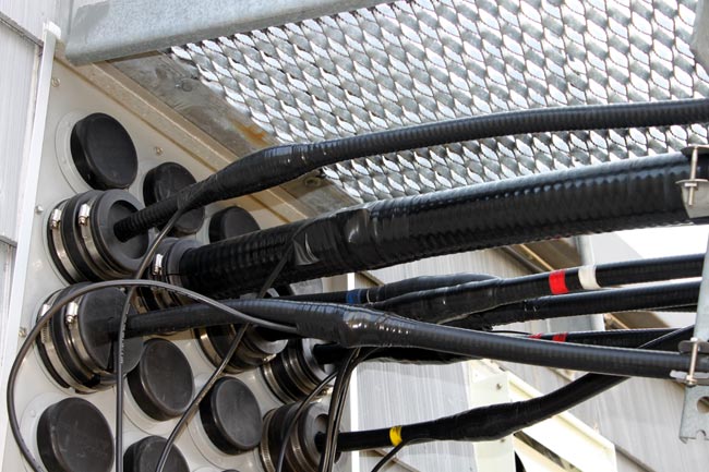
To that end, all coaxial cables that enter the building need to have their outer shields bonded to the site grounding system at the base of the tower and the entrance of the building.  With an FM station where the antenna is mounted at the top of a tall tower, the coaxial cable outer jacket acts as an insulator along the length of the tower.  A lightning strike on the tower will induce a very high potential on the outer conductor of an ungrounded transmission line.  After entering the building, the lightning surge will find the next path to ground, which will likely be a coax switch or the transmitter cabinet.  Neither of those two outcomes is desired.

Thus, it was time to ground the transmission lines at WRKI, the FM transmitter we moved last January.

3 inch coaxial cable grounding kit

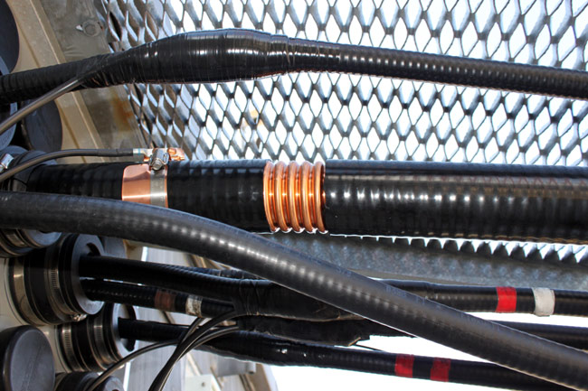
Fortunately, Andrew, Cablewave, Dielectric, and others make grounding kits for various size coaxial cables. They are very easy to apply and make a solid connection between the outer conductor and the site ground.

3 inch coaxial cable grounding kit

The kit contains a copper band bonded to a ground wire, stainless steel clamp, waterproofing, tape, and a pair of bolts.

3 inch coaxial cable properly grounded

The concept of transmitter site grounding is pretty simple and inexpensive to implement.  Thus, it is surprising to me how many transmitter sites, especially older sites, do not have adequate grounding.  That is an accident waiting to happen.

For more on transmitter site grounding, check Nautel’s publication (.pdf) “Recommendations for Transmitter Site Preparation.”

The melted ground wire

I found this on one of the guy wire anchor points for a 400-foot tower:

#2 solid copper wire burned open by lightning strike
#2 solid copper wire burned open by a lightning strike

Had to be a pretty big hit to burn open a #2 wire. This is on one of six guy anchor points for the tower. The ground wire is U-bolted to each guy wire before the turnbuckle and then goes to ground. This was noted between the last guy wire and the ground rod.

It is important to find and fix these things, as the next lightning strike on this tower would have a less-than-ideal path to ground at the guy anchor points, forcing the current to flow through other parts of the transmitter site, possibly through the transmitter itself, to ground.

I generally try to do a brief inspection of towers, guy anchors, lighting, painting, and a general walk around the property twice a year.  That helps prevent surprises like “Oh my goodness, the guy wires are rusting through,” or “Hey, did you know there is an illegal “hemp” farm on your property?”  Well, no officer, I don’t know anything about that…

The Ground Loop

Audio Engineers will know this subject well.  Grounding has many purposes, including electrical safety, lightning protection, RF shielding, and audio noise mitigation.  Although all types of grounds are related in that they are designed to conduct stray electrons to a safe place to be dissipated, the designs of each type are somewhat different.  What might be an excellent audio ground may not be the best lightning ground and vice versa.  Sometimes good audio grounds can lead to stray RF pickup.

The basic ground loop looks something like this:

Ground Loop schematic

Where RG should equal zero, in this representation it is some other resistance.  This causes a different potential on the circuit (V1), which in turn causes current to flow (I1).  It is that unexpected flow of current that creates the problems, causing voltage (V2) to be induced on another part of the circuit.  In cabling applications, this will result in a loud, usually 60-cycle hum impressed on the audio or video being transmitted through the cable.

The resistance can come from something as mundane as the length of the conductor going to ground. This can often happen when using shielded audio wire in installations when the connected equipment is already grounded through the electrical plug.

There are two proven methods for eliminating ground loops, both of which are best implemented in the design phase of construction (aren’t most things).

Radio Station Common Point Grounding

The first is a single ground point topology, also known as a common point or star grounding system.  A common ground system consists of one grounding point or buss bonded together so that it has the same potential.  All grounded equipment is then connected to that point creating a single path to ground.  All modern electrical equipment has a path to ground via the third prong of its electrical cord.  Problems can or will occur when audio equipment is plugged into separate AC circuits, grounded via the electrical plug, and then tied together via an audio ground.  The longer the separate grounding paths, the more severe 60 cycle (or some harmonic thereof) hum can result.

To eliminate this problem, the shields should be broken at one end of the audio cable.  Never cut the third prong off of an electric cord, which can create another problem called electrocution.  Given the choice between a ground loop and electrocution, I’d stay away from electrocution, mine or somebody else’s.

For installations in high RF fields, the open shield or ground drain can act like an antenna.  In those situations, the open end can be bypassed to ground using a 0.01 uf ceramic disk capacitor. Electrically, this will look like an open at DC or 60 cycles, but allow stray RF a path to ground.   This problem can be a common occurrence when studios are co-located with transmitters.

Differential Signaling

The second is by using balanced audio or differential signals as much as possible.  This poses a problem for those stations that use consumer grade components, especially in high RF fields.  For shorter cable lengths, two or three feet, it is usually not a problem.  Anything beyond that, however, and trouble awaits.

It is relatively easy and inexpensive to convert audio from unbalanced to balanced.  As much as possible, equipment and sound cards that have balanced audio inputs and outputs should be used. In the end, it will simply sound better to use higher quality equipment.  Also, longer cable runs need to be properly terminated at both ends.

Installing equipment using good engineering principles and techniques will eliminate these problems before they start.