Even before CONELRAD was introduced in 1951, radio broadcasting was a critical part of the emergency communications infrastructure. The government recognized early on the ability of radio to transmit data and information quickly, over large areas to the general public. It works when all other systems fail, as demonstrated repeatedly over the years, the last of which occurred during Hurricane Sandy last October. Massive destruction from flooding in lower Manhattan and shoreside Brooklyn rendered the electrical grid, telephone network, cellular network, and the internet out of order. Fortunately, enough radio stations stayed on the air and people used battery-powered AM and FM receivers to obtain information.
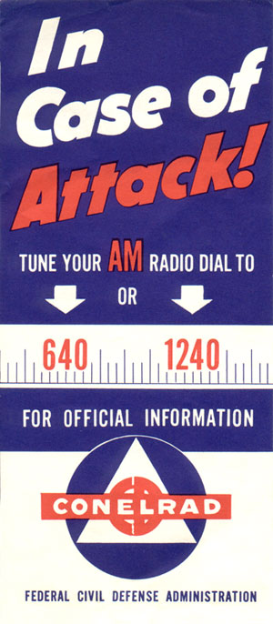
CONELRAD served two purposes; first, radio stations either re-tuned their transmitters to 640 or 1240 KHz or switched off the air. Then, each station that was still on the air would transmit for ten minutes, after which, they turned off and the next station in the chain would turn on and transmit for ten minutes. This was designed to confuse the Soviet bombers flying over the north pole on their way to incinerate us. Secondly, the CONELRAD stations were to distribute emergency information during and after the said attack.

Recently, I found this CONELRAD receiver in a bomb shelter at a radio station. It dates to pre-1963, which is when CONELRAD was replaced by EBS.
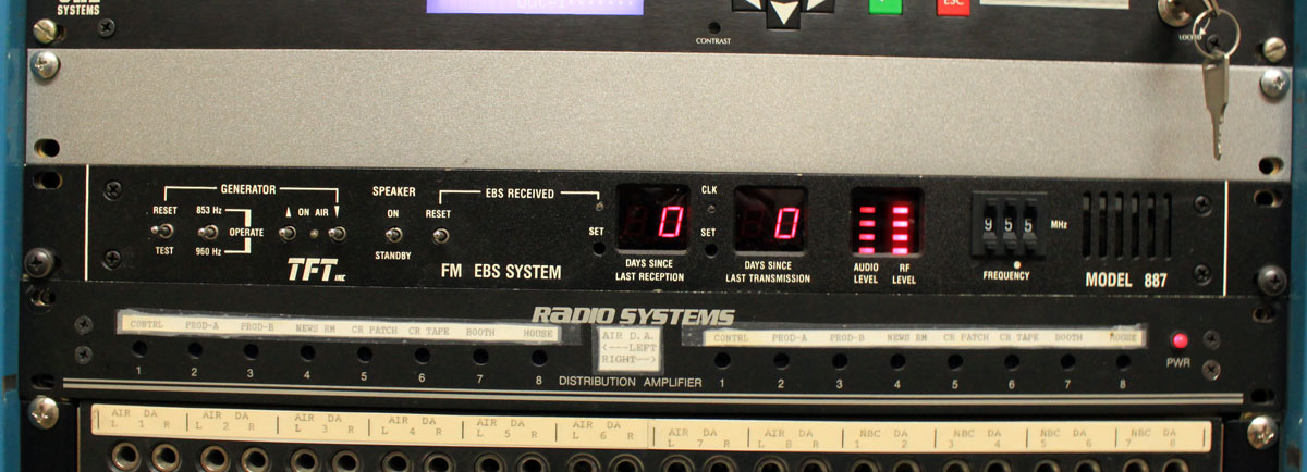
EBS or the Emergency Broadcast System was a refinement of CONELRAD in several areas. EBS used a two-tone attention signal to unmute receivers and alert the public that something important may be happening. Initially designed as a national system to warn of an impending attack, in later years it was also used by state and local governments to warn of other emergencies like weather, etc.
The current system is EAS or Emergency Alert System.
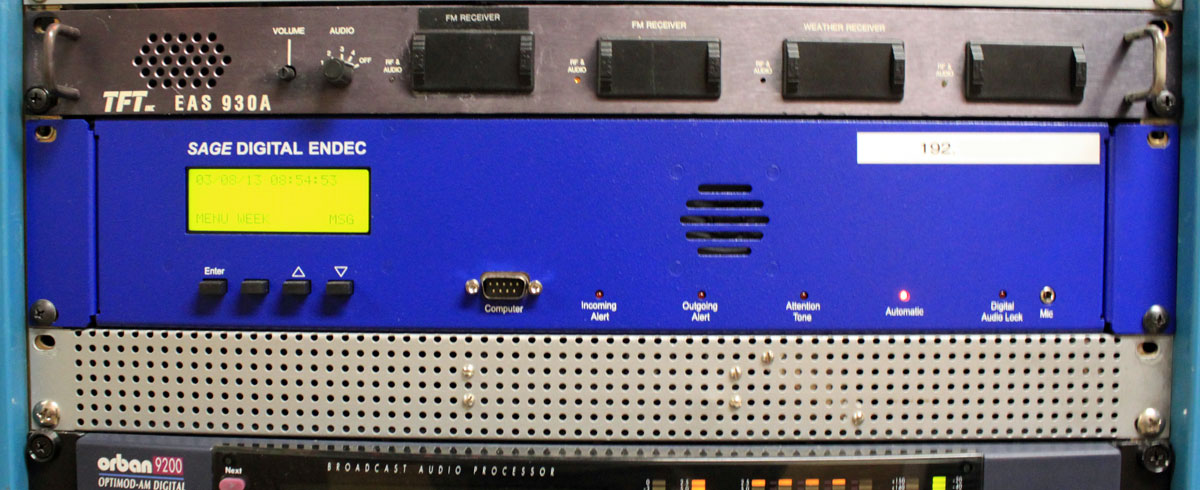
The Emergency Alert System was an advancement of the EBS in several areas. Using SAME protocol in the message headers allowed stations to automate alert message relays. This was driven by the desire for unattended operation. The use of SAME also allowed many different types of messages to be filtered by alert type and area. Each EAS unit also had an internal voice recorder. All of this was upgraded in 2011 with the introduction of CAP, which would take email messages and generate computer voice alerts to be sent out over broadcast stations.
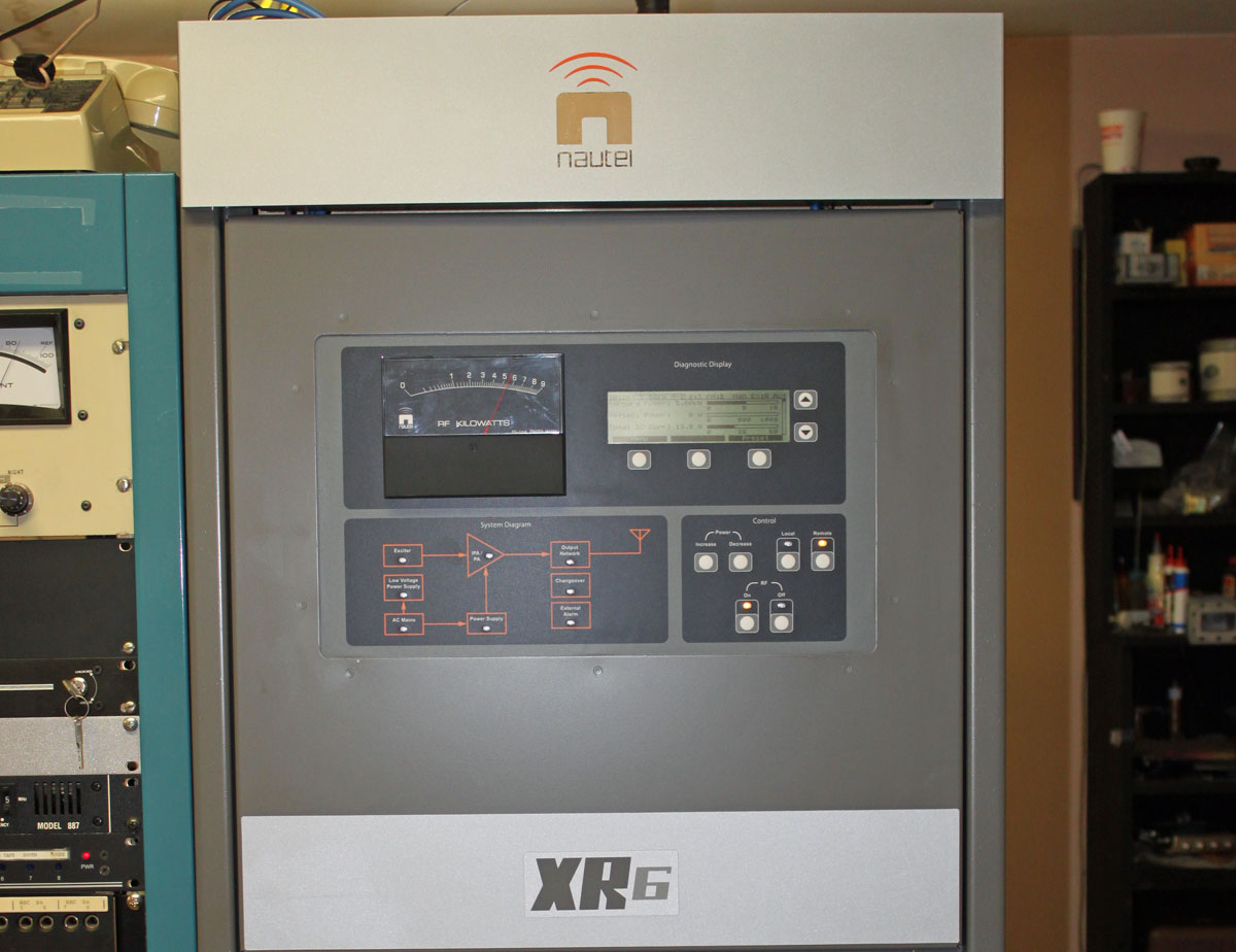
Three generations of emergency communications equipment found at one facility.
The main problem with EAS CAP is it violates the engineering principle of KISS (Keep It Simple, Stupid). It is an overly complicated system that relies on the internet, e-mail servers, the public telephone system, and other infrastructure that may not survive natural or man-made disasters, enemy attacks, or other disruptions. Even something as simple as a national test proved to be problematic in 2011.
For a real emergency information network, the idea of WGU-20 has some merit. Two or more well-positioned medium to high-powered LF stations could serve as a PEP distribution network and reliably cover the entire country. With such a system, every broadcast station, cable head end, and NOAA radio transmitter could monitor the LF stations directly, thus replacing most of the over-the-air daisy chain and or FEMA leased lines. The advantages of LF is that it is fairly immune to HEMP, it goes a long way reliably, can have multiple redundant transmitter sites located within secure areas like military bases, and uses time-proven technology. That would be a real, cold war solution. But no, let us instead rely on a hodge podge of ISPs, TELCO leased lines, 3/4G wireless networks, SMS, satellite links, e-mail servers, and the like, because: Hey! It’s the digital age, we don’t need none of that stinking broadcasting crap.