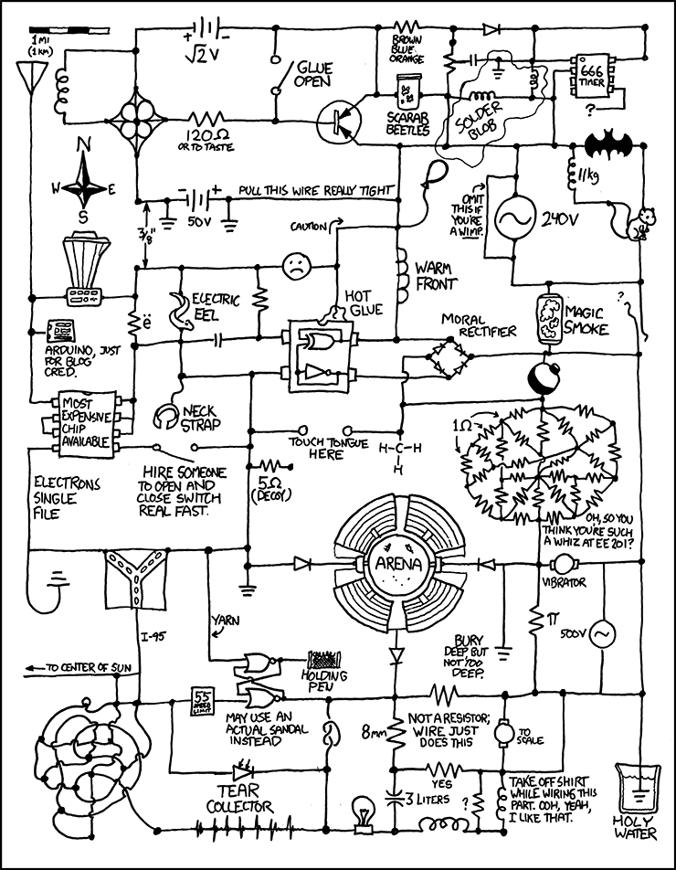
Just in time for the NAB, I’ve been working on this design since my college days. To give you some idea of how long that is, I am nearly 47 years old. I believe it has finally been perfected, now I just need to find somebody to make it. I guess I could send it off to China and get circuit boards made, but they would steal the design.
From the website xkcd.com, which has, perhaps the best website ever published in the history of the internet, here.
Not related to radio engineering, however, I’ve been doing daily radiation measurements at my house (upstate NY) since the Fukushima disaster. A few bits of housekeeping information first: This is a CD V-700 radiation meter, which is a model 6 manufactured by Anton. It was last calibrated in 1986. When I place the Geiger tube over the operational check source, it goes up to about 2 mr/hr as described in the owner’s manual. It may not be completely accurate, but it is accurate enough for this experiment.
This video was taken on March 17, 2011. It sets a good reference for normal background radiation levels:
This video was taken on March 27, 2011. It shows a significant increase in background radiation. Further, much of this appears to be gamma radiation, as the gamma shield is closed during this video:
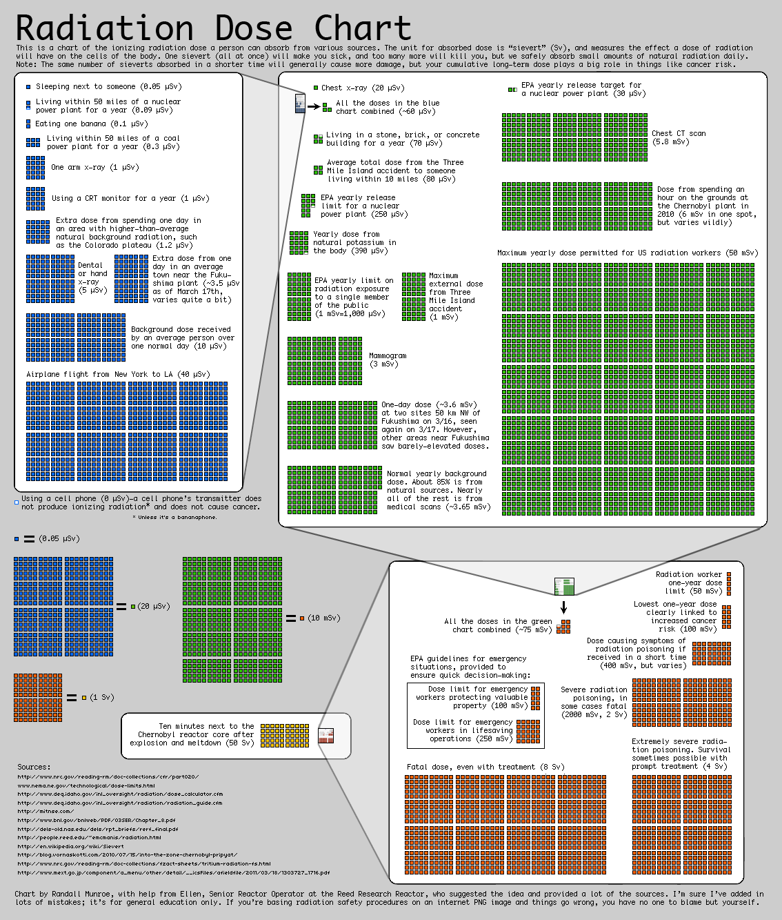
Both of these videos were taken on the most sensitive (x1) setting. It shows that the radiation level is about 8 to 10 times above normal. It is a cause for concern, but not alarm. Not yet. If it continues at this level for several days or weeks, then the overall radiation exposure will begin to accumulate. Right now, it is about the same as taking two NY to Los Angles flights per day, according to this chart (0.35 mr/hr = 3.5 uSv per hour x 24 hours = 84 uSv per day):
Radiation Chart
As of March 28, 2011, the wind has shifted more to the southwest and the levels have dropped somewhat. From our beloved press corps, there have been a few reports here or there on this, most with the standard “this is nothing to worry about” disclaimer. I have also noticed a series of stories and reports that radiation is not all that bad, don’t worry about it, living next to a nuclear plant is fun(!), and we don’t know as much about radiation as we thought we did. I don’t know about all that, I’d rather base my opinion on the scientific body of evidence gathered over the last one hundred years or so. The conclusion of that information is that radiation is bad for human physiology and exposure should be limited.
There is also a crowdsourcing website called “Radiation Network,” which is showing all the levels across the US are normal. This makes me wonder about their instruments and or candor, you can draw your own conclusions.
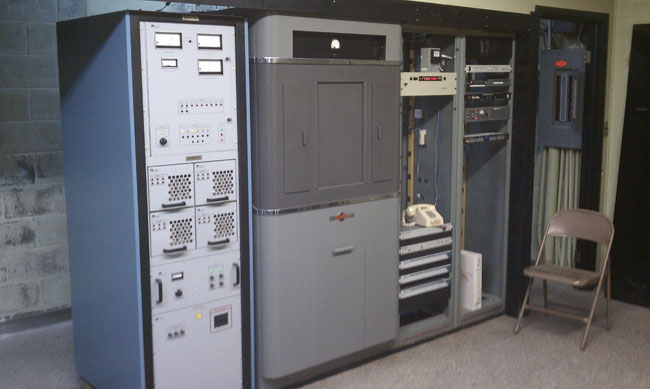
This transmitter is about 10 years old. In ten years of service, there have been no failures. Not one transistor has gone bad. It is connected to a three-tower directional array on 920 KHz.
WGHQ Nautel ND-5 transmitter
Sadly, this model transmitter is no longer made. They were built like tanks, heavy gauge steel cabinets, well-designed, well-grounded circuit boards.
It is dirt simple; RF power MOSFETs on drawers, combined and tuned with the output network. A power supply, exciter, and simple control logic and nothing else. No serial port to plug a computer into, no ethernet ports, no digital read-outs, fancy efficiency optimizing computers, etc. In the meantime, it does what it is supposed to do, stay on the air.
I was reading, with interest, the idea of “energy star” transmitters. I think that good radio station engineers already take electrical efficiency into account when buying a new transmitter. That being said, electrical efficiency is not the only measure of efficiency an engineer should be considering. Reliability, redundancy, and repairability must also be considered. If the station spends an inordinate amount of time on the old backup transmitter while the new, super-efficient main transmitter is off line is counterproductive. Not to mention the time wasted troubleshooting which could be better spent on something else.
Radio stations more and more revolve around networked computers. Engineers need to understand computer networking, especially as it relates to audio distribution and playback. Eventually, I see broadcast engineers being more computer science types rather than electrical engineering majors.
What I have found out about computer networking is this: it is not rocket science. In fact, most of it is pretty easy. Physical networking and cabling are similar to audio and TELOC cabling. Automation computer servers themselves are not difficult to understand as most of them run on some type of Windows program. Other servers such as Apache for WWW and for FTP and streaming run on some type of LINUX OS. LINUX is also not difficult to understand so long as one knows the right command line prompts.
The first part of understanding computers is networking. Without a computer network, a computer is a glorified typewriter. Almost every automation system and or digital editor requires some type of network. Consoles and computers that use AOIP require well-constructed networks in order to operate properly. To that end; cabling choices, network interface devices such as switches and routers, patch panels, and so forth need to be specified and installed with care.
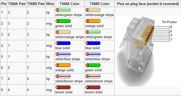
Most often, it is the simple things that will trip an installer up. The one area where I have found the most mistakes made is the pair’s connection to various termination points. There are two basic standards, TIA/EIA T568A and T568B. Neither is better than the other, both are often identified on terminating devices such as jacks and patch panels. The most important aspect of these standards for an installer is to pick one and stick with it.
TIA/EIA 568 color code
When certifying networks, the most common problem I have encountered is crossed pairs. Almost invariably, one end will be punched down with the A standard and the other with the B standard. Jacks are particularly difficult, as the color-coding stickers show both. Many patch panels have a slide-out, reversible card with is an either/or situation. For some reason, I have stuck with the B standard, and on any project I am managing, I get rid of all the A color codes I can find and tell the installers that B is the only acceptable termination standard. That cuts down on a lot of errors and redos during certification. That is good, it saves time and I hate redos.
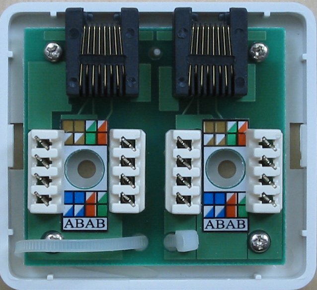
Cat 5e wall jack set
You can see that this color code marking can lead to confusion. I take a sharpie and cross out all the A markings to avoid installation mistakes.
Incidentally, on any new network installation, Category 6 cable should be used. As more and more data throughput is required for network applications, Category 6 Cabling has better performance specs and will likely have a longer service life than another cable. It may be a little bit more expensive than Cat 5, however, well worth the investment. It would be a great mistake and a waste of money to have to pull out the network and reinstall it in a few years because the cabling doesn’t have the required bandwidth.