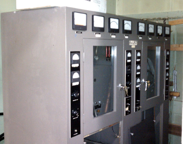
This is a Bauer FB-5000J transmitter, stashed away in the corner of a transmitter site.
Bauer FB-5000J Medium wave transmitter
Sorry I can’t get a better angle on it, as I said, it is stuck in the corner.
I don’t know what vintage it is, it seems to be from the early 1960s or so as it has a low serial number. It ran as the main transmitter until the Harris Gates BC5H was installed in 1976. The transmitter is in beautiful shape, almost a museum piece. I don’t know if it still has all its original iron, as the modulation transformer may have contained PCBs and been disposed of. Otherwise, it is complete and tuned to 1,460 kHz.
I think the owner might be willing to donate it to a reputable organization, preferably a 501(c)(3).
This is standard telephone company stuff, however, it would seem that several radio engineers have forgotten this. I was reading on one forum where an AM station was using 1000 feet of 12 gauge Romex to send audio from the studio to the transmitter out back. The owner was complaining that the audio sounded bad.
Longer wire runs need to be terminated with the characteristic impedance of the cable being used, normally 110 ohms or so for typical audio wire. This is because impedance mismatches can cause return loss just like in an RF circuit. Exactly what the effect of the mismatched impedance depends on the length and frequencies involved. On shorter cable runs of less than 100 feet or so, this usually is not an issue.
The result of return loss is part of the audio energy gets reflected back to its origin (a standing wave), where it mixes with newer audio. This can cause out-of-phase issues and usually, the result is high tinny sounding audio with distortion in the mid-range frequencies. In other words, it ain’t pretty. This can really become an issue with digital audio because of the higher bandwidth requirements for high sample rates. It has always struck me as odd that AES/EBU audio uses XLR-type connectors. An XLR connector does not maintain the characteristic 110-ohm impedance of most digital cables and itself can cause pretty significant return loss. But anyway…
There are a number of options for proper termination:
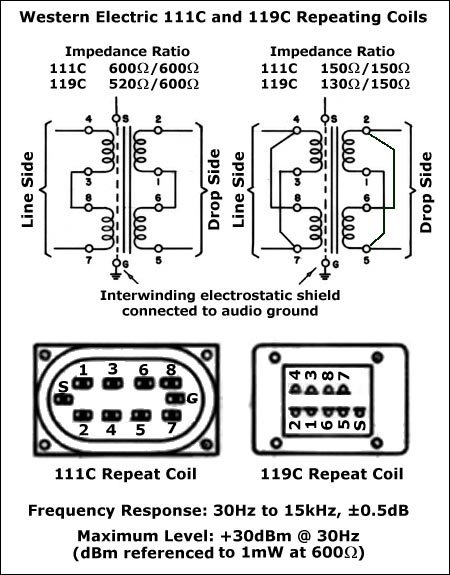
1. Transformers are often used to match the impedances of circuits. A transformer converts alternating current at one voltage to the same waveform at another voltage. The power input to the transformer and output from the transformer is the same (except for losses). The side with the lower voltage is at low impedance, because this has the lower number of turns, and the side with the higher voltage is at a higher impedance as it has more turns in its coil. Western Electric 111C audio transformers were often used in equalized TELCO circuits sending audio over long distances on copper pairs.
WE 111 repeat coil, one of the best such transformers ever made
2. Resistive network impedance matches such as H or T or L pads are the simplest to implement. They limit the power deliberately and are used to transfer low-power signals, such as unamplified audio or radio frequency signals. Almost all digital circuits use resistive impedance matching which is usually built into the structure of the switching element.
H pad impedance matching network
3. Active balanced converters using opamps with high input impedances (10 Kohm bridging resistance) that first greatly reduce the voltage, then amplify it are often used an audio circuits. They have the advantage of active gain control and are often used in conjunction with gain reduction and limiting circuits.
Unbalanced to balanced audio converter
The above diagram shows an active unbalanced to balanced audio converter. The advantages of such a circuit are active gain controls can be added to set levels. With additional feedback circuit elements, it can also be used for automatic gain control, gain reduction, limiting, and so forth.
For most inter and intra-studio wiring, professional audio equipment is designed for 0 dBm 600 ohm balanced audio (AKA line level audio). Audio cables such as Belden 8451 or multi-pair cables terminated on punch blocks or connectors works well. Cable impedances and matching are generally not design considerations. Long cable runs, longer than 150 feet or so, do need to be terminated in a high-quality audio installation.
If you have a shortwave radio and are feeling a little bored lately, late (or early depending on your perspective) at night, tune around to 4625 kHz AM. If the propagation is right, you might hear a peculiar buzzing noise. That is a Russian radio broadcast station, call sign UVB-76, it has been nicknamed “The Buzzer.”
This shortwave radio station has been on the air since sometime in early 1982. Its exact purpose is somewhat of a mystery. It transmits a 0.8-second buzzing sound followed by 1 to 1.3 seconds of silence 24 hours a day, 365 days a year. The station’s transmitter is located about 25 miles northwest of Moscow (56° 4′ 58″ N, 37° 5′ 22″ E) in an area thought to be near the communication hub of the General Staff of the Russian Army. It transmits with a carrier power of 10KW into a horizontal Dipole antenna about 65 feet high.
Dipole antenna for UVB76 transmitter
There are only 3-4 times during its almost thirty-year history that voices were transmitted on the station. They said (from Wikipedia):
At 21:58 GMT on December 24, 1997, the buzzing abruptly stopped to be replaced by a short series of beeps, and a male voice speaking Russian announced: “Ya — UVB-76. 18008. BROMAL: Boris, Roman, Olga, Mikhail, Anna, Larisa. 742, 799, 14.” The same message was repeated several times before the beep sequence repeated and the buzzer resumed.
A similar voice message was broadcast on September 12, 2002, but with extreme distortion (possibly as a result of the source being too close to the microphone) that rendered comprehension very difficult. This second voice broadcast has been partially translated as “UVB-76, UVB-76. 62691 Izafet 3693 8270.”
A third voice message was broadcast on February 21, 2006 at 7:57 GMT. Again, the speaking voice was highly distorted, but the message’s content translates as: “75-59-75-59. 39-52-53-58. 5-5-2-5. Konstantin-1-9-0-9-0-8-9-8-Tatiana-Oksana-Anna-Elena-Pavel-Schuka. Konstantin 8-4. 9-7-5-5-9-Tatiana. Anna Larisa Uliyana-9-4-1-4-3-4-8.
There seem to be two semi-official explanations; One website claims the station is meant to “Transmit orders to the military units and recruitment centers of the Moscow military district,” and the other is the constant buzzer is the High-frequency Doppler method for ionosphere research. Both of these seem implausible since the station was on the air for fifteen years before any voice transmissions and the station’s location is not near any known research facilities.
Naturally, there is a youtube video of it:
Other possible uses include some type of dead hand system. Is Russian, this is called Perimetr or “Hand from the coffin.” It is an automatic or semi-automatic launching system for nuclear ballistic missiles. In theory, if an incoming first strike is detected, the system is turned on and it waits for input from the military leadership. If none is received, as would be the case if all military and civilian leadership were killed in the first strike (as the so-called “decapitation strike,” or more recently “shock and awe”), then the surviving nuclear weapons would be launched automatically in a retaliatory strike.
Think of something like 4 8 15 16 23 42
Is this the true purpose of The Buzzer? The only ones who really know are the Russians and they, of course, are not saying anything.
If this radio station is used in a system like that, I would imagine that there are radio receivers tuned to 4625 kHz at Russian military installations. That frequency likely propagates well to most of the Russian landmass. In addition to an automated launching system, it might also be used as a “communication of last resort” type system. If the buzzing stops, an alarm sounds, and the speaker un-mutes. This would be a good reason to use AM vice some other type of pulsed or digital modulation scheme, which would likely perform better for an automated system.
If that is the case, then we each should say a little prayer every night that UVB-76 aka “The Buzzer” keeps on buzzing.