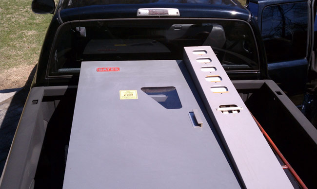
After replacing a burned-out FM antenna for one of our clients, the question became; what do we do with the old antenna? There were several options:
- Throw it behind the transmitter building and let weeds and poison ivy grow over it
- Take it to the scrap yard to get whatever money we could for it
- Give it away to somebody
- Turn it into a fountain
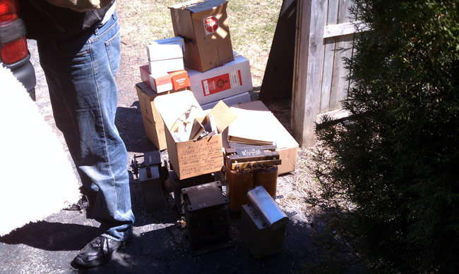
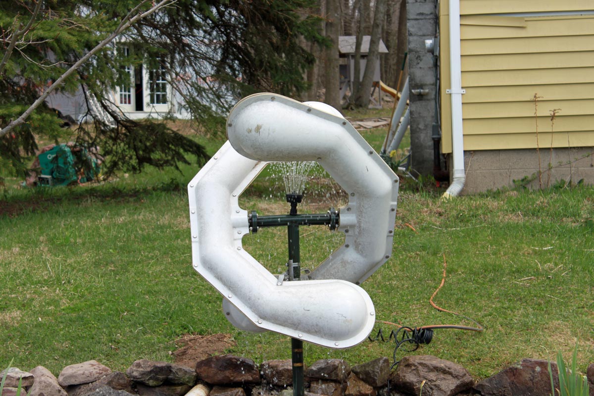
I have scrapped these old antennas before, they are made mostly of hard yellow brass, which does not net too much at the scrap yard. In fact, by the time I finished removing the Radomes and separating the metal, I had more time for the job than it was worth for both myself and the client. Therefore, I present to you the ERI LPX lawn fountain:

Upon completion, my wife and daughter, who are natural-born skeptics, even had kind words to say. It seemed like a simple project at first; enlarge the dry well for the basement sump pumps and install some type of mounting base for the old antenna. It turned into a little more than that.

It took several hours of backbreaking labor, a concrete form, and a few bags of ready-mix concrete to create the mounting base. Several wheelbarrow loads of gravel, some rocks from the old wall in the woods, and a pond pump from the hardware store round out the installation.
I am not sure what else to say.