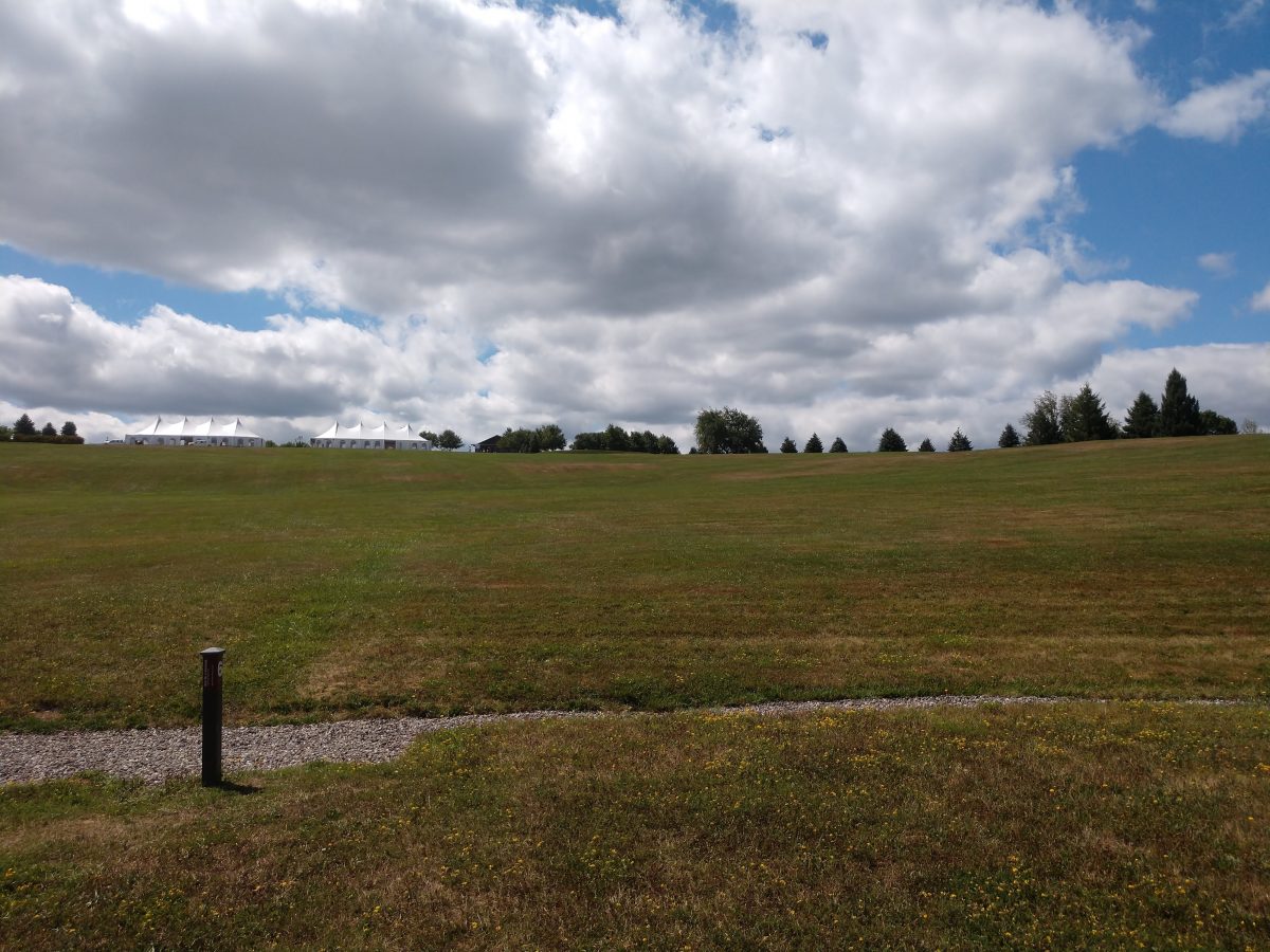
I regret not having enough time for writing these days. There are a number of reasons for this. Firstly, much of what I do running my business is mundane and not worth noting. For example; today I am going over work reports and reconciling the bank account. Necessary, but about as exciting as watching the grass grow or reading about drying paint.
However, the rest of the time I have been working on various projects around the northeast, to wit:
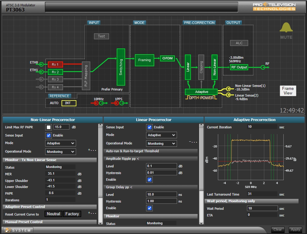
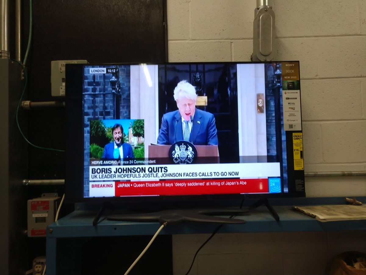
In Boston, I took part in converting an LPTV station to ATSC 3.0. That was interesting and I am enjoying the TV work.
In Syracuse, we had to lower a TV transmitter from the 23rd floor to the 22nd floor on the outside of the building. The transmitter itself became marooned because an electrical conduit for an alarm system was installed restricting the size of the stairwell.
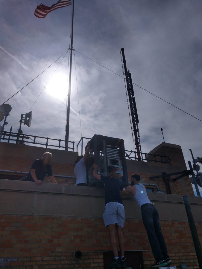
Fortunately, we hired a moving company to do this. I am pretty sure that our insurance does not cover damages from transmitters falling 22 stories.
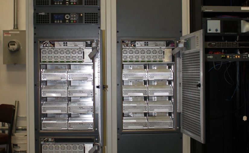
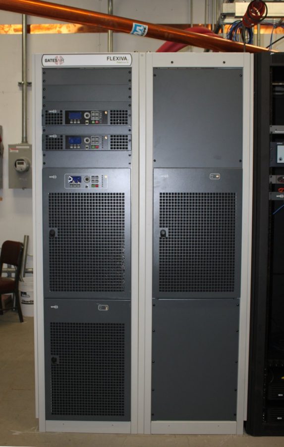
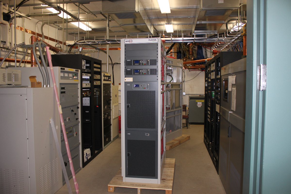
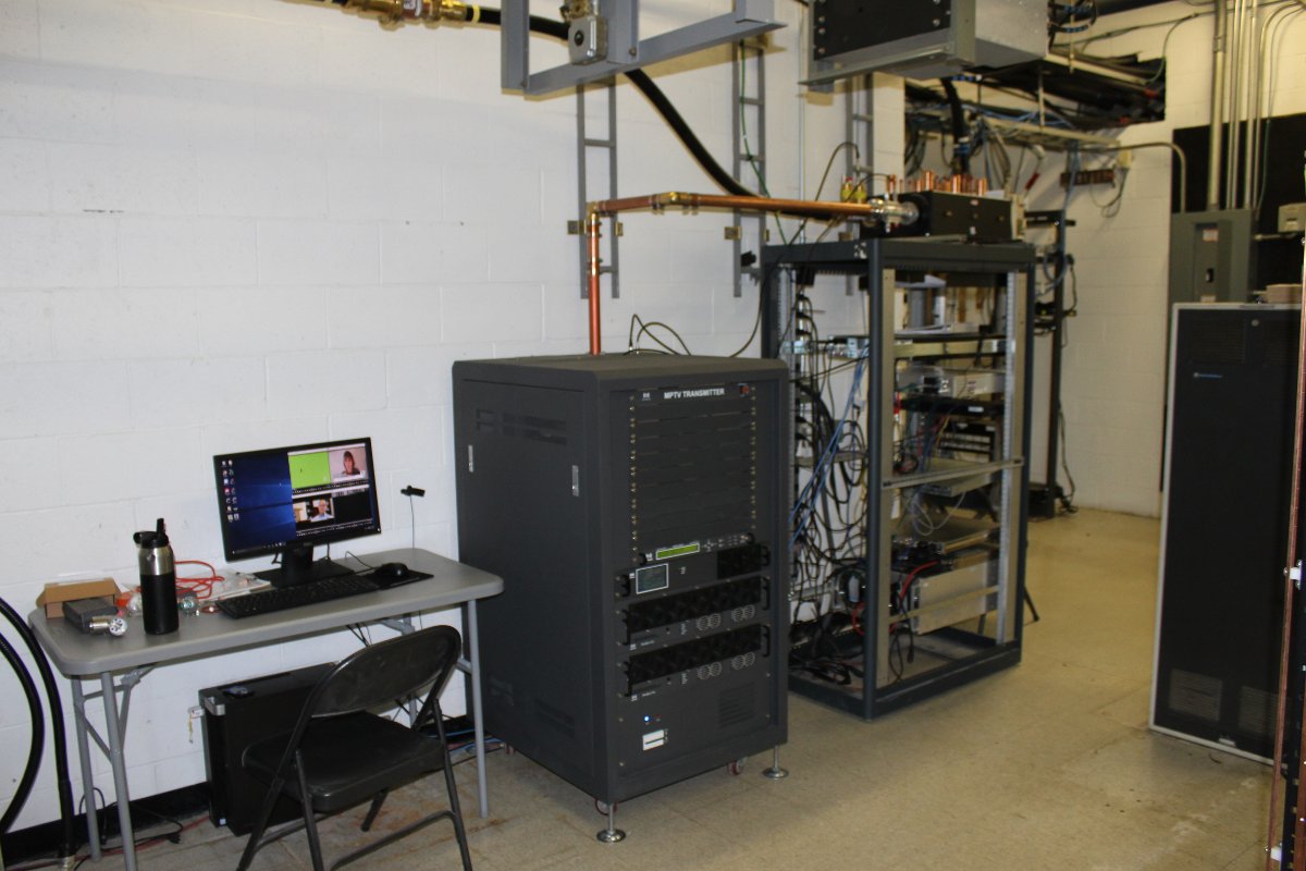
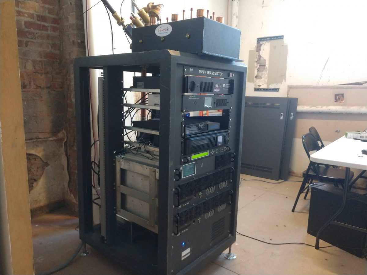
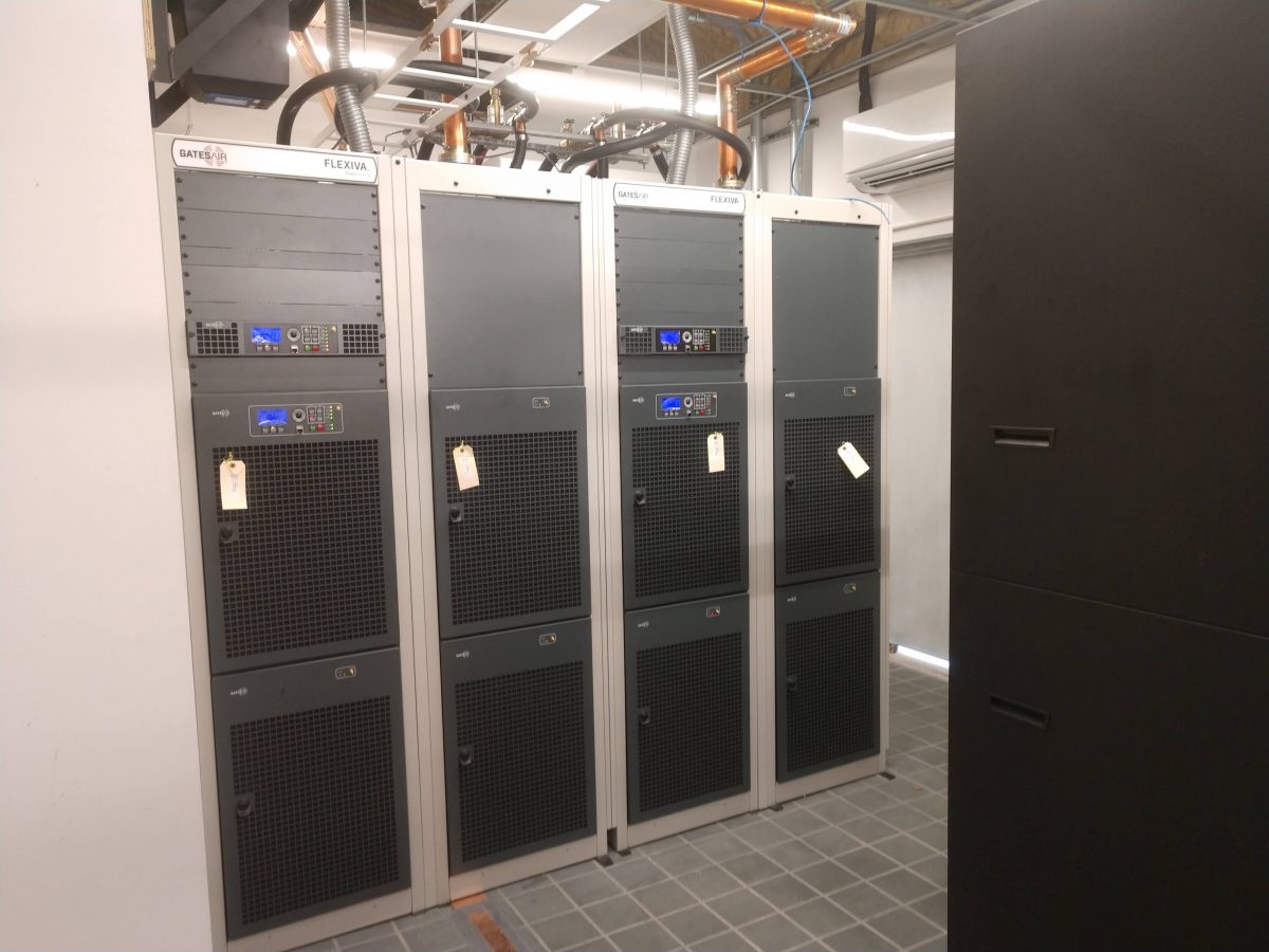
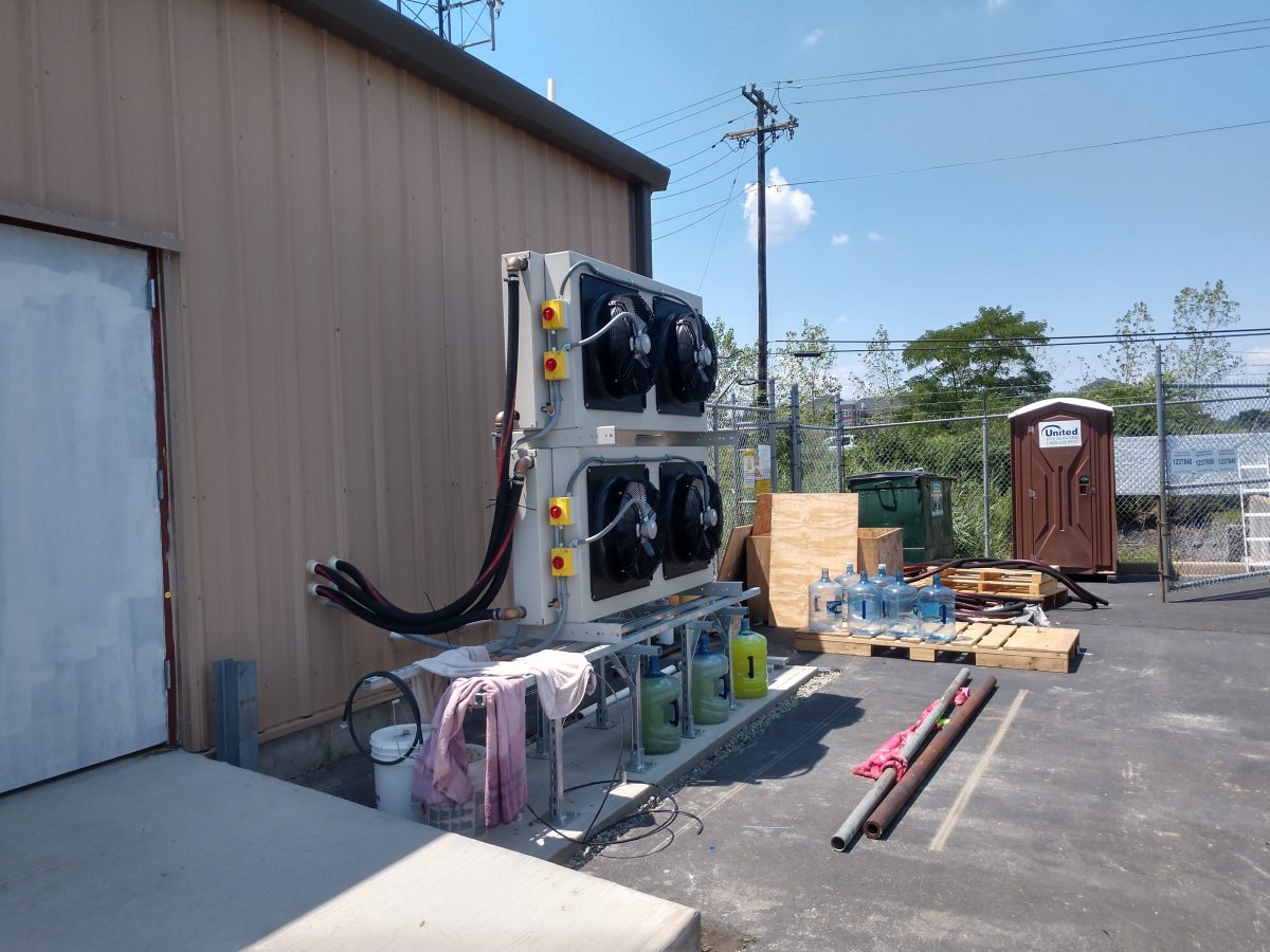
In NYC, I installed two FLX-40 transmitters for GatesAir.
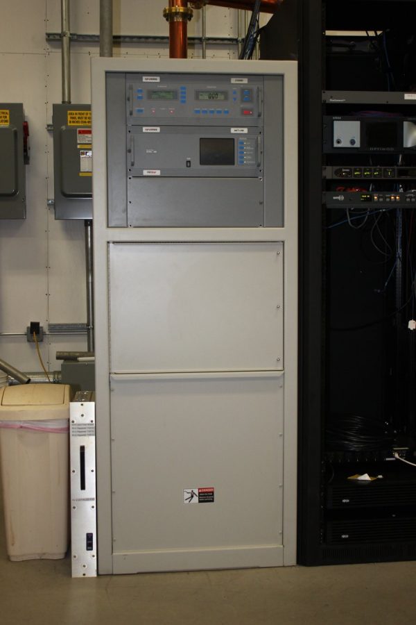
In Kingston, NY a used BE AM1A (along with a coax switch and dummy load) was installed at WKNY.
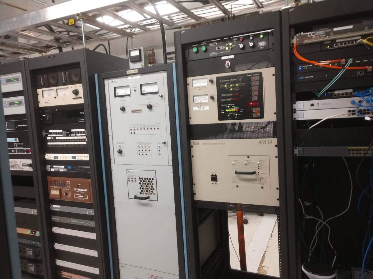
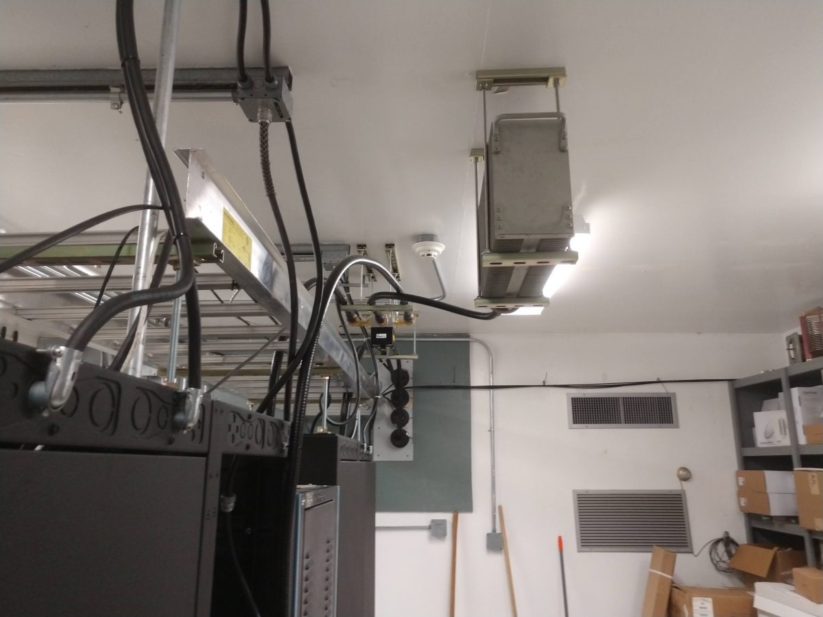
It is nice that this station has a decent backup transmitter to buttress the aging, yet very reliable Nautel ND-1.
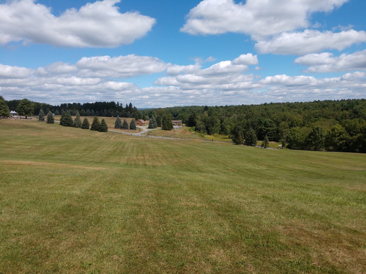
Even though it is a short drive away, I had never visited the 1969 Woodstock Music and Art Fair site in Bethel, NY. It was interesting and being sort of an audiophile, I enjoyed this exhibit in particular:
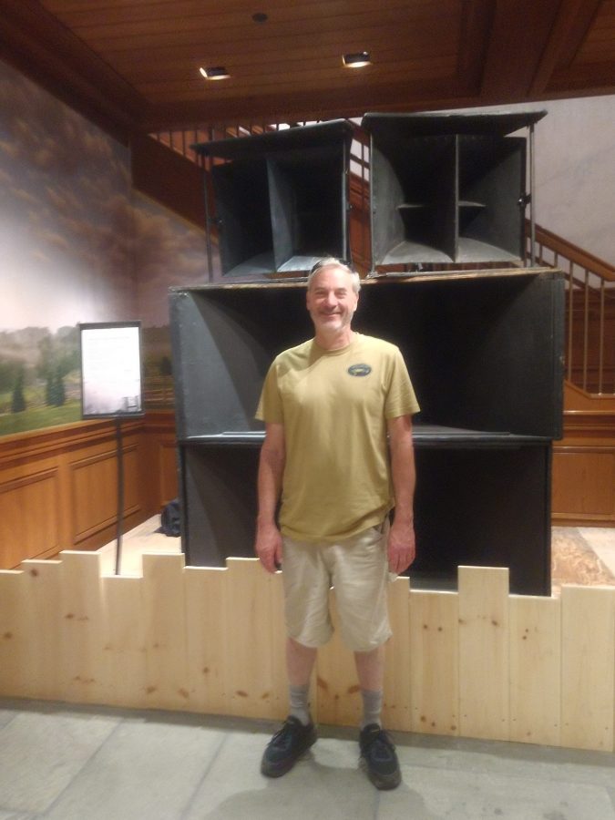
From the display:
This speaker stack sat on scaffolding high in the air… festival sound engineer Bill Hanley custom-built eight speaker cabinets for Woodstock, amplifying music and stage announcements across the large festival site… Afterward, the design would be known in the industry as the “Woodstock Bin.”
Bethal Woods Performing Arts center Museum, August 10, 2022
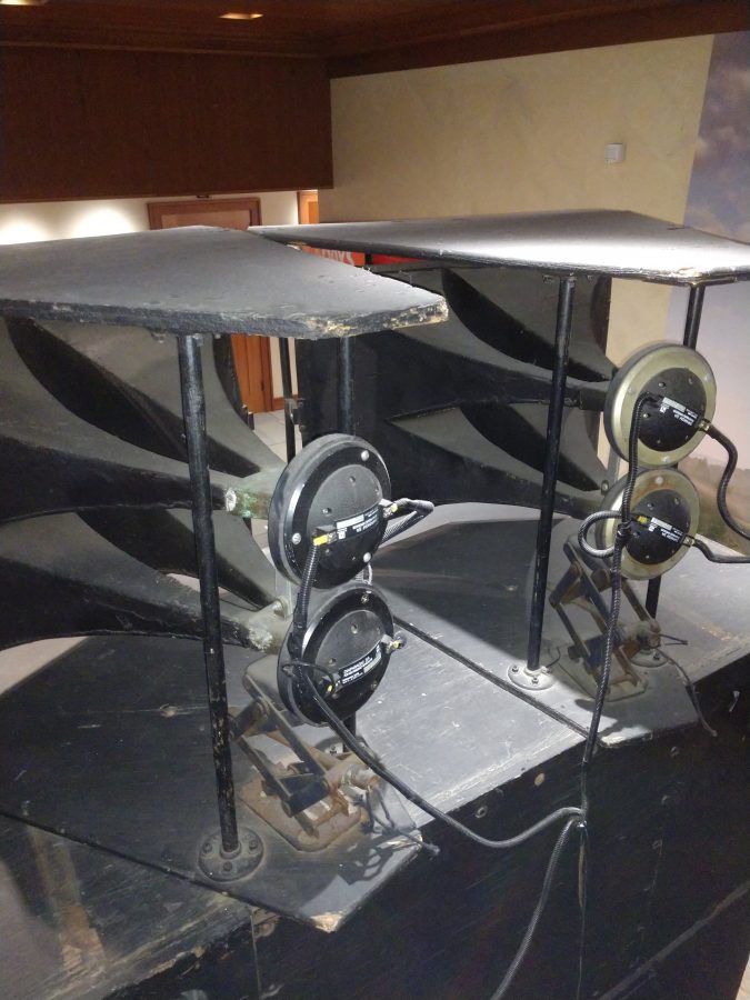
The high-frequency horns used Electrovoice diaphragm S/A compression drivers. I don’t know which driver was used for the bins.
I am also writing articles for Radio Guide, I hope that you are enjoying them!