Nautel Radio Coverage Tool

This is a Webinar video from Nautel about their Radio Coverage Tool:

Highlights of the Nautel RF tool kit:

  • Analyze the proposed transmitter location’s coverage
  • Tower heights can be adjusted
  • Antenna gains can be changed
  • Transmitter power levels
  • Includes Terrain data
  • Includes population within coverage areas
  • Frequency Range 30 Mhz to 3GHz
  • Useful for general broadcast or point-to-point systems

This can be a useful tool for those looking to gauge the realistic coverage of a station in terrain-challenged areas.  It can also be useful for studying STL paths, RPU coverage, etc.

One problem is the power levels and antennas are preset, with the minimum setting of 200 watts into a two-bay antenna.  These settings are too high for use when investigating a potential LPFM.  For that, Radio Mobile Online (which is the engine behind the Nautel RF tool kit) can be accessed directly via www.ve2dbe.com/rmonline.html.  Requires an account, which is very easy to set up.  For most users, FM broadcast band frequencies will not be available, however, 2 meter amateur frequencies (146 MHz) are the default, and for all practical purposes, will model coverage in the FM band (88 to 108 MHz) just fine.

By creating a hypothetical LP100 transmitter site, the coverages between the FCC 60 dBu contour and the actual coverage based on terrain can be compared.  This is the FCC 60 dBu coverage contour:

Example contour, LP-100 station
Example 60 dBu contour, LP-100 station

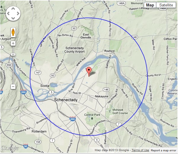
According to the US Census data, this station has a population coverage of; 30,721 in the 70 dBu or 3.162 mV/m contour, 92,574  in the 60 dBu or 1 mV/m contour, and 165,183 in the 50 dBu or 0.316 mV/m contour. Courtesy of REC Network.  The 60 dBu contour is considered the protected area licensed for use by the FCC.

Looking at a coverage terrain map, the picture changes somewhat:

Example coverage map, LP-100 station

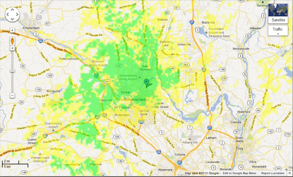
This is based on predicted receiver location using terrain data; receiver antenna height 1 meter, 90% reliability, minimum signal level 10 µV (20 dBu,  yellow, very good car radios) and 31.62 µV (30 dBu, green, good radios and indoor reception).  Areas to the south and east of the transmitter are shaded by a large hill, thus they show low or no signal on the terrain based coverage map.  UN Population data indicates the yellow has 178,573 and the green area has 72,014 persons.  This map does not take into account co-channel and adjacent channel interference, which there is sure to be.

When comparing the two maps, one can see the coverage holes in the terrain map that are within the 60 dBu contour.  There may also be a slight difference in populations covered because the FCC map uses 2010 US Census data and the Radio Mobile Map uses UN population data.  For general planning purposes, the area shaded in green would be a safe bet on good reception, all other things being equal.

Since the LPFM stations are very limited in their ERP, finding a good transmitter site that will cover the desired area will be key to a successful operation.

Now where is that BNC male to N female adaptor

Working with RF can produce some head scratchers.  Most transmitter manufactures tend to use the same type of connector for things like exciter RF outputs and composite inputs.  Over the years, I have become well stocked with all sorts of BNC and Type N connectors.  Satellite equipment uses Type F connectors, Analyzers use Type N, Oscilloscope uses BNC,  GPS equipment uses SMA and so on.  Except when they don’t.  As any good engineer will tell you, when they don’t will be in the middle of the night at some mountain top location while the station is off the air.

After one such incident, I invested in a TPI-3000A adaptor kit.  This kit has both the male and female versions of Type N, F, SMA, BNC, TNC, UHF, UHF mini and RCA.  They can be mated in any combination using the Universal interface.

TPI 3000A adaptor kit

On more than one occasion, this little kit has meant the difference of between being back on the air or driving down the mountain to look for an in between series adaptor.  A couple of recommended additions include a 7/8″ and 1 5/8″ EIA flange to type N male.

TPI-3000A inside
TPI-3000A inside

They can be a little pricey, however, I have seen several for sale on eBay for less than $100.00.  The key to not loosing the various little parts to this kit is to write a little note detailing the date and location where the adaptor was used,  then stuff it in the empty hole.  Hopefully, when permanent repairs are made, the adaptor will be retrieved.

OET65? What is that?

Readers of this blog will know that I enjoy history.  Old photos are great things to study, as they say, pictures… thousand words… etc.  Here is one that I found on the RadioMarine website:

WER radio, 192X?
WER radio, 192X?

Here we have three gentlemen at work at an early radio station.  It seems like a posed shot, nobody can study a meter that intently.  They are sitting directly in front of the transmitter and it looks like the antenna tuning coils are behind the operating position.  Notice the open wire and transmission line, presumably all under power when this picture was taken.  There seems to be no concern about RF or electrical safety, I suppose it was trial and error back then, with a heavy price paid for error.  Meter boy should be careful not to back up too far, if he does, he’ll get a little behind in his work.

We’ve been a little busy this last week, I’ll catch up on the blogging this weekend, there are many things to tell.

Repairing a solid state FM transmitter module

We have a Harris Z5-CD transmitter for one of our FM stations.  Brand H is not my preferred make, however, it was already installed when we bought the station, so I have to live with it.

This particular site gets hit by lightning strikes often.  Normally, it does not affect anything until the transmitter gets turned off for maintenance.  Then, almost invariably, when turning the transmitter back on one of the modules will fail.  Most often this is manifest when one of the two power supplies shut down causing the transmitter to run no more than 20% power.

The way this is troubleshot is to slide each module out and turn the transmitter back on.  When the power supply stays on, the bad module has been located.  A confirmation test is to check the MOSFET for a short circuit between Drain and Source.  This short circuit condition puts a direct short on the power supply causing it to crowbar and turn off.

So, once the bad module has been located, and the spare module is installed in the transmitter, then what?  Most engineers call Harris and ship the module back for repair.  Most engineers don’t want to mess with unsoldering a surface mount MOSFET and soldering a new one in.   I find it moderately entertaining to fix things myself, so I do not do what most engineers do.

NXP BLF177 MOSFETS
NXP BLF177 MOSFETS

The MOSFET in this particular module is the BLF177, made by NXP.  Harris will sell you one for quite a bit of money.  You can also buy one from Mouser for about half the cost.

Harris FM Z series transmitter PA module with cover removed

Once the parts are obtained, the worst part of the entire job is unsoldering the old MOSFET.  This takes some patience and skill.  What I found works best is to melt some solder on the foil leads and get them good and hot.  Since this MOSFET is already destroyed, we don’t have to worry about heat, etc.  The one thing you do not want to do it actually break the MOSFET open.  That is because it contains beryllium oxide, a known carcinogen.  Once all the solder is liquid, carefully pry the foil up with a small screwdriver.  There are several components that have to be moved to work on this.

Harris Z series PA module with MOSFETS removed

After the old MOSFET is removed, clean up the solder pad with a solder pump and solder wick.  I like to use a little liquid flux on the solder wick, it makes things go faster.

Once all the old solder is cleaned off the solder pads, I brush a light coat of liquid flux in the pad.  Again, this makes things go faster.

Harris Z series FM transmitter module new MOSFETs waiting to be soldered

The new MOSFETS are very sensitive to static discharge, so I always use a static drain wristband when handling them.  I place both MOSFETs onto the circuit board.  I then solder them on using as little heat as possible from the soldering iron.  Again, the MOSFETs are sensitive to heat and one can easily be destroyed if it gets too hot.

Harris Z FM series PA module repaired

This is the module with the new MOSFETs soldered in. I use defluxing compound to remove all the extra flux. Once it cools off, I test the new module with a DVM:

Harris Z series FM PA circuit board under test, resistance is 3.3 Mohm

If the MOSFETS are good, they will have an internal resistance of around 3.3 MΩ.  If the module is bad the MOSFETS will read only  a few ohms if shorted:

Harris Z series FM PA module under test, DVM reads 1.6 ohms

That is how you do it.  I think Harris charges $775.00 per module to repair.  I fixed this one for $240.00, but that is not the reason I did it.  I did it for the fun that was in it.