Radio facilities, particularly mountaintop transmitter sites, are prone to power transients. The causes can be varied, but most often, lightning is the culprit. Long power transmission lines to the site are vulnerable to direct strikes and EMF-induced spikes from nearby strikes. Other issues, such as switching transients, load fluctuations, and malfunctioning equipment can lead “clear weather” outages. Of course, the best way to deal with such things is through prevention.
Power line surge suppressors have been around for quite some time. They usually take the form of a MOV (Metal Oxide Varistor) connected between the hot leg and neutral or ground. There are a few differences in designs, however. Typically, most facilities employ a parallel surge suppressor. That normally takes to form of an enclosure hung next to the main power panel with a group of MOV modules in it. The MOVs are fed from a circuit breaker in the panel. Like this:
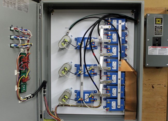
LEA parallel or shunt surge suppressor
This is an LEA three-phase 208-volt shunt surge suppression unit, which has MOVs between all phases to ground and each other. That is connected in parallel to the electrical service with the circuit breaker disconnect. These function well enough, provided there is a good bit of series inductance before the unit and also, preferably after. The series inductance can come from many sources, including long secondary leads from the utility company transformer or electrical conductors enclosed in metal conduit, particularly rigid (verses EMT, or FMC) metal conduit. The inductance adds a bit of resistance to the transient voltages, which come in higher than 50 or 60 Hz AC waveform.
A better method of transient protection is the Series Surge Suppressor. These units are installed in line with the incoming service and include an inductor to add the required series resistance coupled with MOVs and capacitors. Most series surge suppressors also filter out harmonics and RF by design, something desirable, particularly at a transmitter site. Series surge suppressors look like this:
LEA DYNA systems series surge protector
This is an LEA three-phase 240-volt unit. As in the other example, all phases have MOVs to neutral and each other. There are MOVs and capacitors on the line and load side of this unit (the line side is the bottom of the inductor). A basic schematic looks like this:
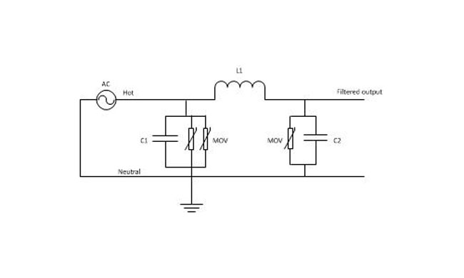
Series surge suppressor basic schematic
A few things to note; MOVs have a short circuit failure mode and must be fused to protect the incoming line from shorts to the ground. MOVs also deteriorate with age, the more they fire, the lower the breakdown voltage becomes. Eventually, they will begin to conduct current at all times and heat up, thus they should also be thermally fused. MOVs that are not properly protected from overcurrent or over-temperature conditions have the alarming capacity to explode and/or catch on fire. From experience, this is something to be avoided. Matched MOVs can be paralleled to increase current handling capacity.
The inductor is in the 100 µH range, which adds almost no inductive reactance at 60 Hz. However, it becomes more resistive as the frequency goes up. Most transients, especially lightning, happen at many times the 60 Hz fundamental frequency used in power distribution (50 Hz elsewhere unless airborne, then it may be 400 Hz).
Capacitors are in the 1-10 mF range and rated for 1 KV or greater as a safety factor. The net effect of adding capacitance is to create a low-pass filter. Hypothetically speaking, of course, playing around with the capacitance values may net a better lowpass filter. For example, at 100 uH and 5 mF, the cutoff frequency is 225 Hz, or below the fourth harmonic. Care must be taken not to affect or distort the 60 Hz waveform or all sorts of bad things will happen, especially to switching power supplies.
These units also need to have a bypass method installed. If one of the MOV modules needs to be replaced, power to the unit has to be secured. This can be done by connecting it to the AC mains before any generator transfer switch. That way, the main power can be secured and the site can run on generator power while the maintenance on the surge suppression unit is taking place.
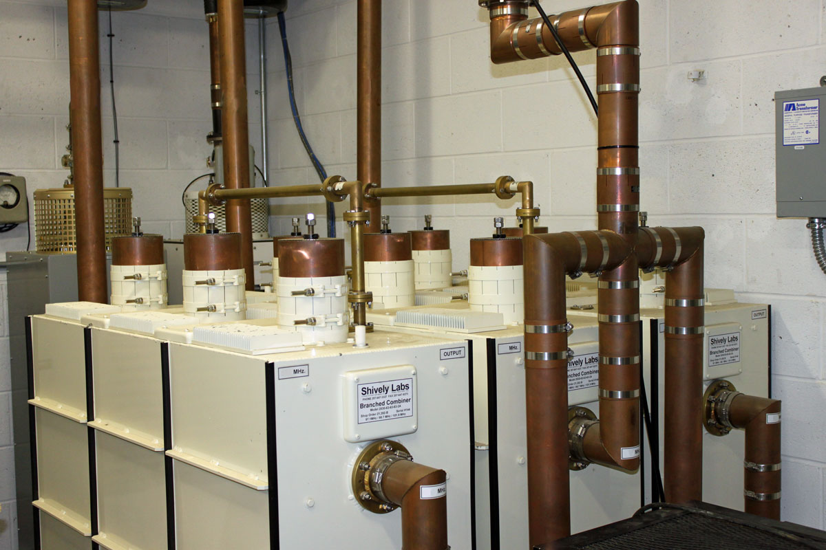
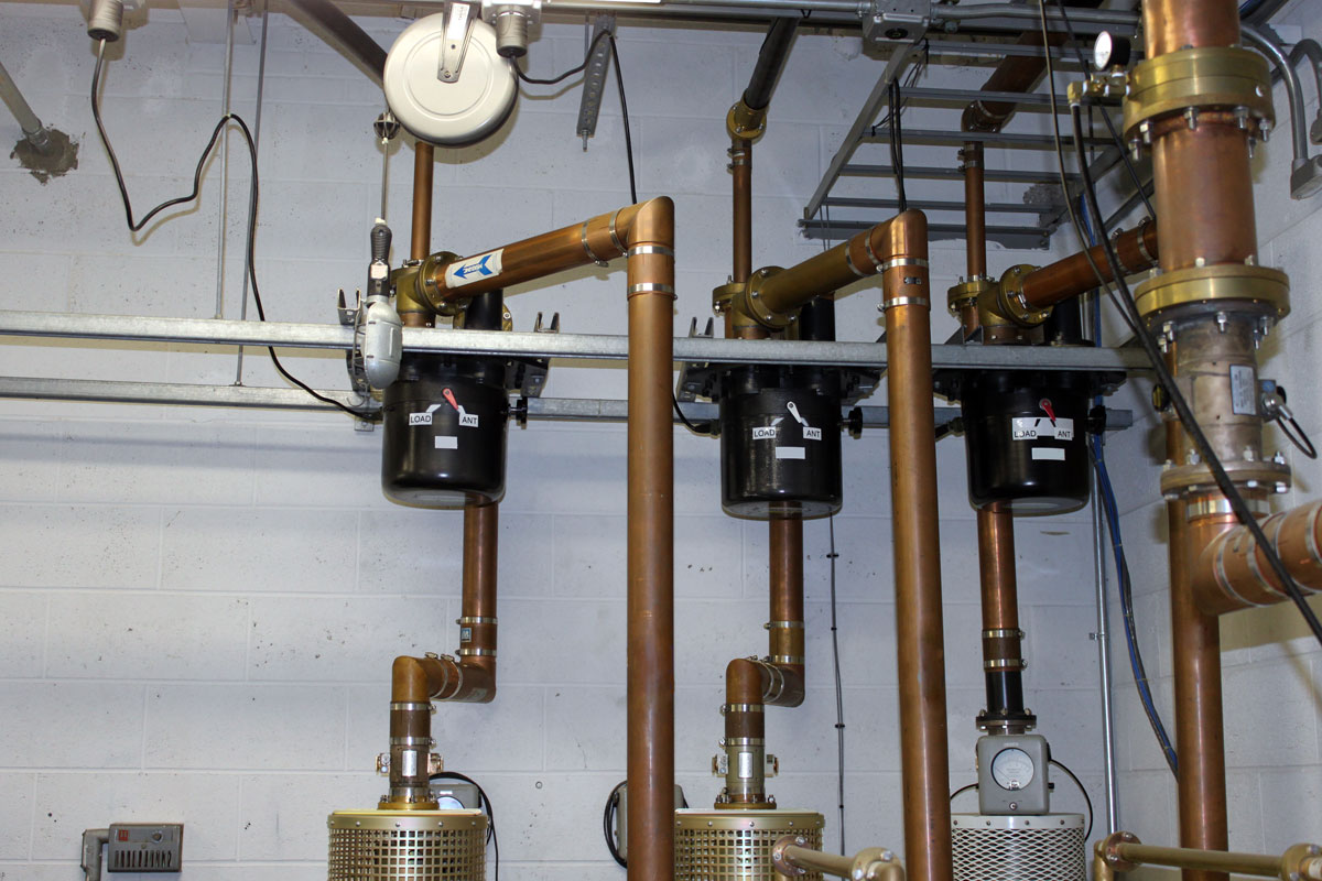
This transmitter was retuned from 107.9 to 92.9 and put back into service. Retuning an HT35 transmitter is no small matter, there are 32 pages of retune instructions. This unit is now in service as the main transmitter for WEZF, Burlington, VT.
The transmitter power output is 22,000 watts into a four bay, three around panel antenna, which gives it an ERP of 46,000 Watts at a height of 824 meters (2,703 feet) above average terrain. The tower is at the summit of Mt. Mansfield, which is 1,340 meters (4,395 feet) above sea level.
Mount Mansfield TV and FM antennas
This is the Mt. Mansfield FM transmitter room. There are two TV stations in this building as well.
Final frames are of the WVPS Nautel NV-40 transmitter.
Last year, the main antenna and transmission line for WSPK was replaced. I was, therefore, somewhat surprised to hear that there was an issue with the new transmission line. And yet, problems there are. Most likely, some ne’er do well has shot the transmission line with a bullet making a hole, which, when it rains, allows in water. Said water then accumulates in the bend at the bottom of the tower. When enough water is present to fill the gap between the center conductor and the outer conductor, this happens:
Foward and Reflected power meters, WSPK, Mount Beacon, NY
For those of you keeping score at home, that’s 980 watts forward, 375 watts reflected or about 4:1 VSWR. Obviously not a good load, in fact the transmitter shut down. Fortunately, the backup transmitter and antenna system worked flawlessly.
This began happening last month, usually after a heavy rain storm. Thus, I went out to the base of the tower and shook the transmission line and sure enough, water was sloshing around in there. Last time time it happened, a tower crew was summoned to inspect the line. Inspect it they did, but did they find any holes? No, they did not. Perhaps the issue is with the antenna itself, in which case the entire thing will have to be removed from the tower and lowered to the ground. In the mean time, my boss drilled a small “weep hole” at the bottom of the bend where the line comes off the tower.
I uncovered this weep hole and pressurized the line and viola, lots of water came out:
WSPK 1 5/8 inch air dielectric transmission line, Mount Beacon, NY
A bit unconventional, but effective nonetheless. The first video is of the water dripping out:
The second video is of me walking back into the transmitter building to pressurize the line:
Everything is very noisy because it is Monday, when all the generators on site exercise. There are five diesel generators running while I was videoing recording this.
I would estimate about 6 ounces of water came out through the weep hole, most of it landing on the ladder underneath. After the water was drained out, the transmitter came back on at full power and normal VSWR.
A temporary fix to get the station back on the air. The real repair work will begin when the antenna comes down to be inspected.
Update: The tower climbers did find a hole in the transmission line, just below the flange that connects to the antenna. It looks like a pencil sized gash just before the line bends back to the tower. Lightning? Rifle bullet? Damage while installing? We can’t really tell. They installed a patch over the hole which holds about 3 psi line pressure. We then used a vacuum pump to evacuate the line, then recharged with dry nitrogen.
Regarding Pedro’s question below in the comments: Since we found this problem quickly and were able to evacuate the line, there should not be any corrosion, that is our hope. Time will tell