As more and more things that use radio are invented, it is inevitable that the limited spectrum will be squeezed. We see this with BPL, which admittedly causes interference on the HF spectrum, however, proponents have deep pockets. Then there are the so-called “whitespaces” between active TV channels coveted by broadband providers. Not even the once-sacred GPS system is immune to interference by other radio systems being implemented by companies who “bought” the radio spectrum in question. Although it is quite beyond me exactly how one can buy or sell radio spectrum. I suppose next they will be selling sunlight and rain.
The next chunk of the RF spectrum being repurposed is in the 451-457 MHz range. This has already been eyed by the Department of Homeland Security for on-scene data communications networking. However, the latest interested party is the Alfred Mann Foundation, which builds bonic implants. In an interesting twist, one of the plans for the spectrum in question is something called the MMNS (medical micropower network systems). This network would be used to transmit commands from the patient’s spinal cord to prosthetic devices.
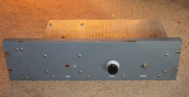
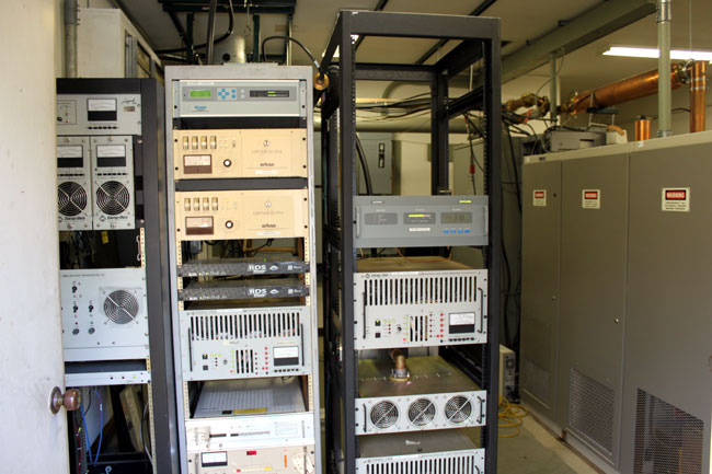
Many TV stations use 450-455 MHz band for IFB and cueing. Radio stations use that same spectrum for remote broadcast and telemetry return links from transmitter sites. RPU frequencies used to be very congested, as remote broadcasts were often an additional revenue stream for radio stations. These days, most stations to “cellphone” remotes, e.g. the disk jockey goes out to a store or event and calls it in on his or her cellphone. Some of the more fancy stations use POTS codecs like the Comrex blue box or matrix and very few still use ISDN. So the first question is how many broadcasters still use UHF (or even VHF) RPU gear (AKA The Marti)?
The second question is what type of damage or reaction could occur if a UHF RPU interfered with one of these MMNS devices? Some RPUs use fairly high power levels and directional antennas. But, according to FCC Report and Order on ET Docket 09-36, it is a done deal:
The rules we adopt will allow these new types of MedRadio devices to access 24 megahertz of spectrum in the
413-419 MHz, 426-432 MHz, 438-444 MHz, and 451-457 MHz bands on a secondary basis.
It goes on to say:
Each year, millions of Americans, including injured U.S. soldiers, suffer from spinal cord injuries, traumatic brain injuries, strokes, and various neuromusculoskeletal disorders. The devices that we anticipate will operate under our new rules are designed to provide artificial nervous system functions for these patients.
Which is nice. I suppose if someone is at the mall setting up the Marti for a remote and when it gets turned on, Grandpa starts break dancing, one should find another frequency. Do you think the DJs or promotions people remember that? No, me neither.
If this keeps up, eventually everything is going to interfere with everything else and nothing will work.