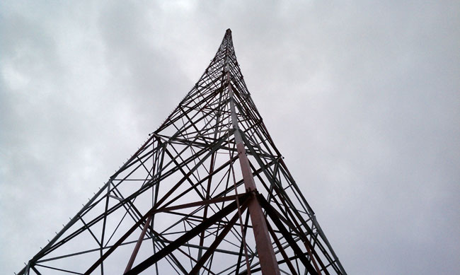
Broadcasters historically have tried to remain on the air during emergency events like major storms, earthquakes, and other forces of nature. Oftentimes, commercial power is interrupted, and thus, the backup power generator is installed. Propane-powered generators for medium duty (power up to 45 KW) are popular because of the decreased environmental hazards, availability and expense of fuel, and ease of maintenance and repair. This sized generator can run the critical loads of a studio facility or a transmitter site with TPOs between 5 and 10 KW.

Most propane generators use a gasoline engine modified to use propane. These generators can also use natural gas, however, because natural gas has slightly less energy, the generator’s service rating is reduced by about 10 percent.
The biggest error I consistently see with propane generators is improper fuel tank sizing. It might seem just fine to plop a 500-gallon tank down next to a 45 KW generator and expect everything to be just fine. 500 Gallons may sound like a lot of fuel, but the more important consideration is tank vaporization, that is to say, how fast the liquid propane can be removed from the tank for use. Propane fuel companies should be able to size these things correctly, most of them have books and charts that tell what capacities and sizes are needed. However, as a general troubleshoot guide, the following information is provided:
Generator manufacturers will specify how many BTU per hour a generator will require under full load. If not, these are some conservative rules of thumb:
- For every 1 KW of electrical generation, 2 horsepower of the engine is needed*
- Under full load, each horsepower will consume 10,000 BTU per hour*
- Propane has 92,000 BTU per gallon
- Propane weighs 4.2 pounds per gallon
*Note: These are not the figures you will find in your engineering handbooks, they are adjusted for generator winding and engine efficiency.
Propane Tank Vaporization Rates (Continuous BTU/hr vs volume at tank temperature):
| Size propane in a tank (assumes 1/3 full) | Maximum continuous BTU/hr at degrees F | ||||
| 0° | 20° | 40° | 60° | 70° | |
| 120 | 129,600 | 188,640 | 247,680 | 308,160 | 338,400 |
| 150 | 146,880 | 213,790 | 280,700 | 349,200 | 383,520 |
| 250 | 253,800 | 369,400 | 485,000 | 603,480 | 662,700 |
| 325 | 321,300 | 467,670 | 614,000 | 763,900 | 838,900 |
| 500 | 396,270 | 567,700 | 757,300 | 942,240 | 1,034,700 |
| 1000 | 708,480 | 1,031,230 | 1,353,980 | 1,684,600 | 1,849,900 |
| 1450 | 816,120 | 1,253,400 | 1,645,690 | 2,047,550 | 2,248,480 |
Note: Tank vaporization depends on fuel level, tank temperature, and withdrawal rate. The above chart is a conservative generalization and represents a safe median value.
If a propane tank cannot vaporize fuel fast enough, the generator will begin to run lean, eventually overheat, and shut down. The vaporization rate depends on the tank temperature, which drops as fuel is withdrawn. For the above-cited 45 KW generator called to duty after a severe winter storm, the tank would need to vaporize: 45KW x 2 HP = 90 HP. 90 HP x 10,000 BTU/hr = 900,000 btu/hr. A 500-gallon tank is too small for that size generator.
As the tank temperature drops a propane tank can develop frost on the outside of the tank, even on a hot summer day, which compounds the problem.
The correct size tank for a 45 KW generator is 1000 gallons. This can also be two five-hundred-gallon tanks connected in parallel via a high-pressure line.
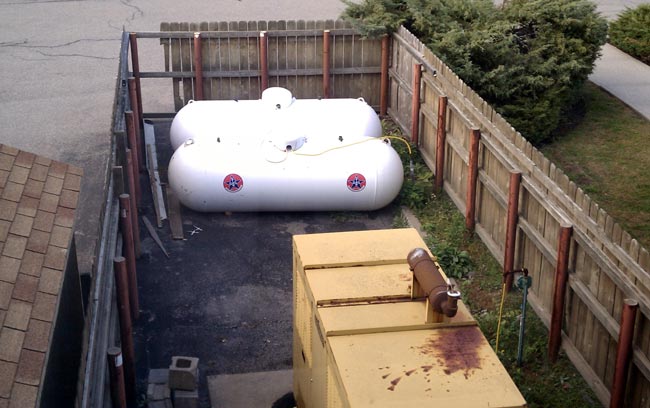
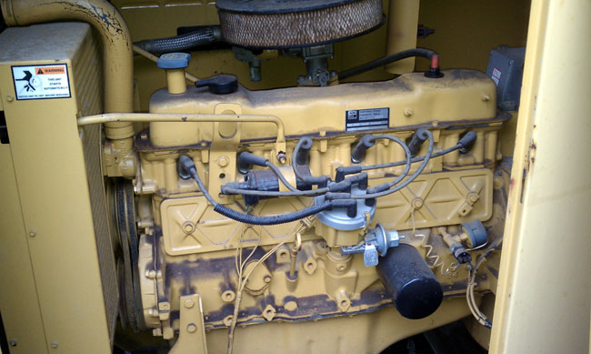
Also note, the generator’s radiator is facing the tanks so that when the unit is running, hot air is blowing on the tanks, warming them up. This particular generator is about 25 years old, which is why it looks a little worn. It still carries the load and mechanically is in sound condition.
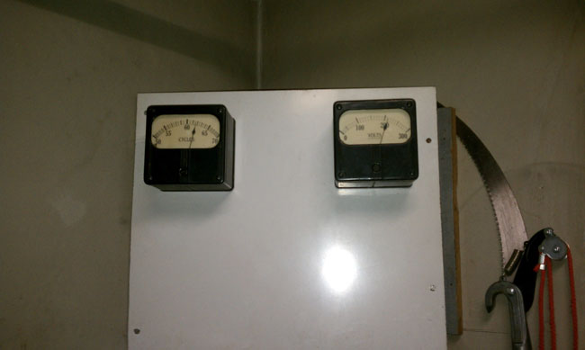
Most propane fuel systems have two regulators; one high-pressure regulator on the tank, which takes the variable tank pressure and steps it down to about 10 PSI, and the vaporizer which steps the pressure down to a few ounces per square inch (or inches of water column) and adds air creating propane gas for the generator to burn.
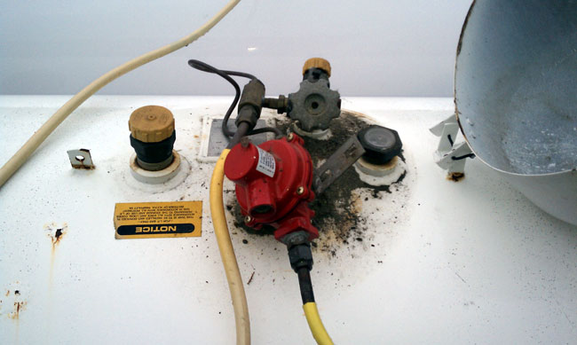
It is important that the vaporizer be mounted above the snow line and that there is a little screen on the air intake, otherwise, mud wasps will build a nest in the air intake and the next time the generator is required to run, it won’t start.

Fuel piping is also a concern, if the low-pressure lines are not large enough to handle the required BTU, the generator will run lean, creating the same problems as an improperly sized tank. Different piping has different capacities, see the following charts:
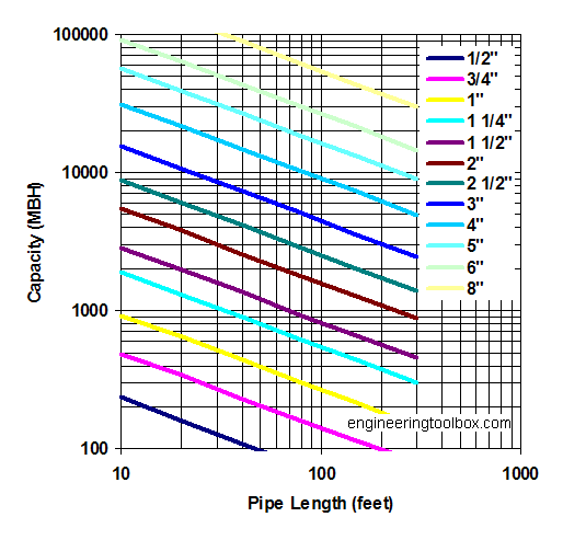
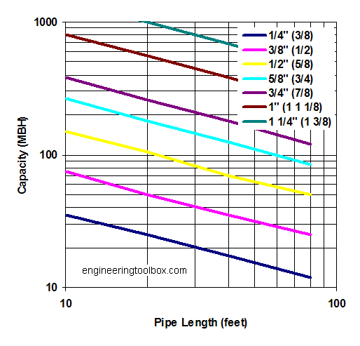
Assumes pressure less than 1.5 PSI, one MBTU is equal to 1,000 BTU per hour.
Once the generator is installed, maintenance is required. As a minimum:
- Exercise the engine bi-weekly for 15 minutes. Propane generators do not need to run under load.
- Check fuel, oil, and antifreeze levels monthly, more often if heavy use.
- Change the oil, oil filter, and air filter, and check the antifreeze freeze point, and battery electrolyte specific gravity yearly
- Change out belts and hoses as needed, and pay close attention to the block heater hose, this is where leaks often develop
- Clean out mice nests and droppings as needed
Mice love generators.