The imminent demise of ISDN has been talked about for some time. There now appears to be a date attached which makes it semi-sort of official. As of May 18, 2013, Verizon will no longer accept orders for new ISDN lines. They will also not make any changes to existing lines and will start charging more for the service.
Taking the place of ISDN will be a variety of Ethernet/IP-based audio transmission methods. As technology evolves, this makes sense. The quality of ISDN and the bidirectional nature was a vast improvement over the old system 5/7/10/15 KHz point to point analog lines. The one downside, ISDN equipment was expensive and the service was expensive to install and operate.
High-speed internet is available in almost every business and venue. Many times, there is no cost to access it and equipment is relatively inexpensive. Depending on the equipment, CODEC, and speed, it can sound almost as good as ISDN. For those opposed to using the public network due to reliability issues, there is always frame relay.
With the advent of fiber optic cables starting in the 1980s, the majority (one estimate says 99%) of this country’s overseas communications are carried by undersea cables. These are interesting system constructions, being first redundant and second, self-healing. Glass fiber stands themselves are fairly fragile. Bundling several together and then sinking them in the ocean can create mixed results. Deep ocean bottoms are often very rugged, containing mountains, canyons, and fault lines. Thus the submarine cables used have to be pretty rugged.
There is a common misconception that fiber optic cables do not need repeaters. That is not true, while they do not need as many repeaters as copper cable, repeaters are still required approximately every 40-90 miles (70-150 km) depending on the cable type. These active devices are another failure point. Overall, it is a complex system.
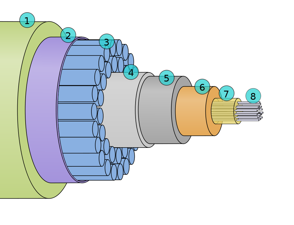
Submarine Fiber Optic Cable cross-section, courtesy of Wikipedia
Cross-section of a submarine fiber optic communications cable:
1. Polyethylene 2. Mylar tape 3. Stranded metal (steel) wires 4. Aluminum water barrier 5. Polycarbonate 6. Copper or aluminum tube 7. Petroleum jelly 8. Optical fibers
It weighs about 7 pounds per foot, which is pretty hefty.
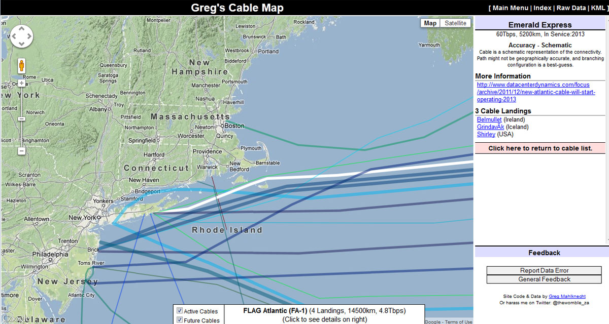
There are a couple of interactive maps online that have detailed information about where these cables go, date in service, and data capacity. My favorite is Greg’s Cable Map which is a Google map with cable data overlayed with a downloadable KML file:
Undersea cable map
This shows a new cable called the “Emerald Express” which is going into service in 2013. Throughput is reported as 60 Tbps, which is moving right along. As noted on the map, this is more of a schematic diagram connecting two shore side points. The path the cable takes is an estimate and the actual geographical location may (is likely to) be different. Click on any line on the map for cable information. Most cables have their own web page and Wikipedia article.
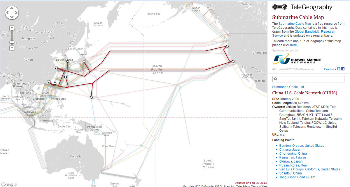
Another undersea cable map is the Telegeography Submarine Cable Map, which has many of the same features noted above:
China US submarine Cable network diagram
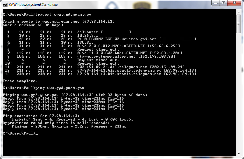
Just in case you were wondering, as I often do, how a TCP/IP connection is being routed to any given place. For fun, I tried a trace route to a known server on Guam and found the results interesting:
Trace Route, Guam
Approximately 231 ms round trip route from NYC to LA to Guam and back, which is over 8,000 miles (12,850 km). A few of the intermediate routers did not answer and I tried this several different times; the same routers time out. This missing information looks to be small steps, not large ones. So, which cable goes directly from LA to Guam? Possibly the China-US Cable Network (CHUS) (picture above). At 2.2 Tbps and landing at San Luis Obispo, that is the likely candidate for the cable that carried my data.
As a general exercise, it is kind of fun, although it may be harder to figure out a particular route to say London or Berlin because there are many more different possibilities.
Route latency is something to keep in mind when planing out AOIP connections for remotes and other interactive type connections between studio and remote location. Almost nothing is worse than that half second delay when trying to take phone calls or banter back and forth with the traffic reporter.
Lately, I have been working at a site in West Orange, NJ connecting various parts and pieces, and thought that this was interesting:
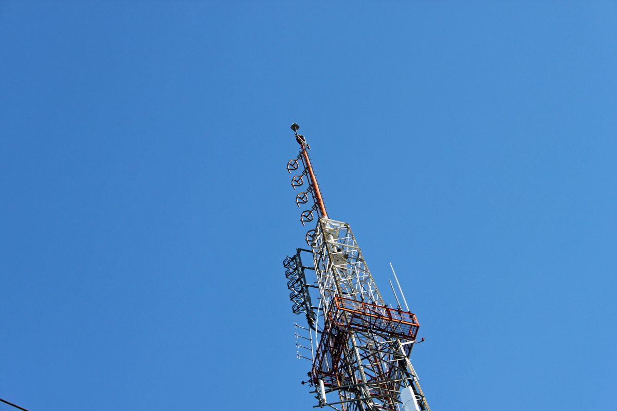
WNSH 94.7 MHz, Newark, NJ main antenna (top)
That is the main antenna for WNSH, 94.7 MHz Newark, NJ, aka “Nash-FM.” Below that is the backup antenna for WEPN-FM (98.7 MHz), WQHT (97.1 MHz) and WFAN-FM (101.9 MHz). More on those stations later.
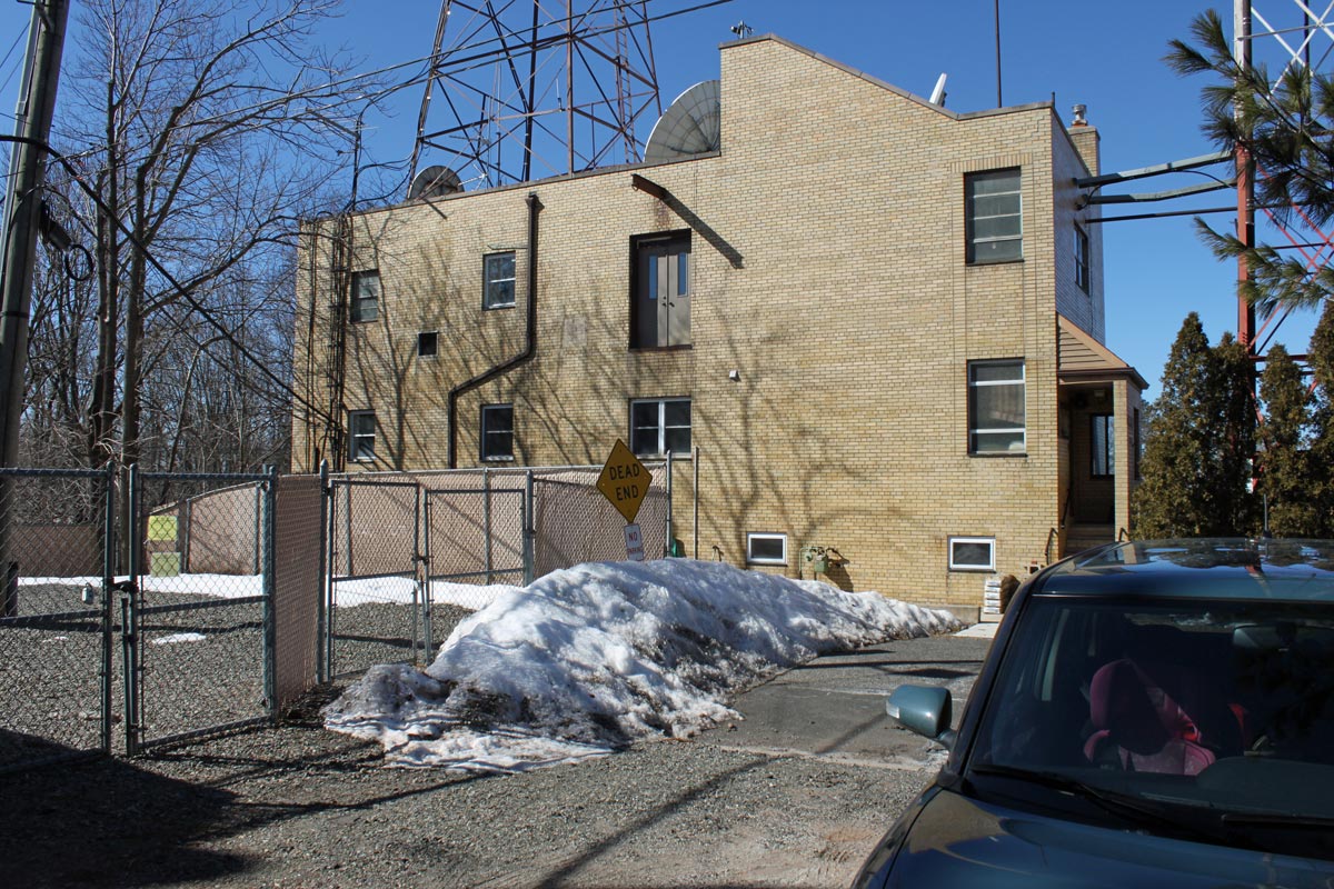
WFME studio building
This is the WFME studios, located off of NJ Route 10. It is kind of hard to see the call letters behind all those trees and whatnot. There is an older picture from 1999 floating around, which shows the studio building in better condition. This is a better angle:
WFME studio
I believe WFME is still originating its programming here, now being broadcast on WFME 106.3 MHz, Mount Kisco. I had to use the facilities there, the interior is like a way back 80’s time machine, which is kind of cool. If I owned a radio station, I would go for the 70’s office decor; dark wood paneling, shag carpets, bright blue bathroom tile and avocado green appliances, but hey, that’s just me.
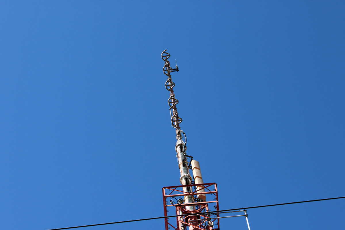
WNSH backup antenna, WFME-TV antenna
This is the WNSH backup antenna, mounted on top of a UHF slot antenna for WFME-TV. There is an LP TV antenna mounted there also, but I don’ t know who it belongs to. Overall, it is an interesting transmitter site on “First Mountain” in West Orange, NJ. Also located here, WFMU-FM, an old ATT microwave site, now owned by American Tower and several cell carriers. In other words, it is just like most other mountain top transmitter sites, except there is a shopping plaza across the street.
I gave a listen to the NASH while driving there. For where it is, it seems to have a pretty good coverage area. As for the music, well, I am not sure how a Manhattenite will relate to Tracy Byrd’s “I’m from the Country” wherein:
Everybody knows everybody, everybody calls you friend You don’t need an invitation, kick off your shoes come on in Yeah, we know how to work and we know how to play We’re from the country and we like it that way
Being from upstate NY, I get it. Perhaps the Manhattan salary man will too. There are no DJ’s on air quite yet, just music, some commercials and a few “Nash-FM” liners that sound slightly distorted.
FM and AM broadcast radio processing has gone through many iterations. At first, the main processing function was to limit the input audio to a transmitter and prevent over-modulation. This was a particular problem with early tube-type AM transmitters, where over-modulation could create power supply overloads and kill the carrier while engineers scrambled around resetting things and hopefully pressing various buttons to get the transmitter back on the air.
Over the years, processors incorporated not just limiting, but compression, gating, equalization, clipping, and so on all in an effort to keep ahead or at least abreast of the station across town.
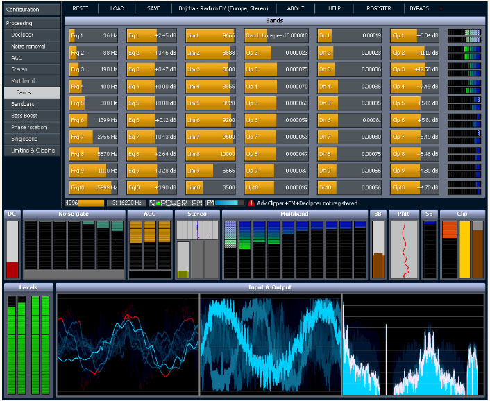
Today, broadcast air chain processors come in all shapes and flavors. In addition to that, internet streaming stations have their own unique set of issues to deal with. The top-of-the-line Telos Omina or Orban Optomod systems are great, however, they can set one back a pretty large sum of money. Enter then, the Stereo Tool PC based software processing program.
Stereo Tool sofware screen shot
The first difference between, say the Omina and Stereo Tool is the end user decides the hardware and basic operating system. The second difference is Stereo Tool comes with a free trial. Then there is the price difference, which ranges from about $48.00 US for the basic version, to $161.00 US for the basic FM version and finally $269.00 US for the full version (actual prices are in Euros, which will fluctuate day to day and the credit card company will likely charge an exchange fee). Add to that a medium-speed (2 Ghz) Intel Pentium4 or better computer, 1 Gb or more of RAM, good sound card and it all comes out to a reasonably priced audio processor.
Here are some of the specific features for broadcasting:
The idea of PC-based audio processing is new and interesting to most of us. The designer and owner of Stereo Tool, Hans van Zutphen, was nice enough to answer a few questions I posed to him via email:
PT: What prompted you to write audio processing software?
HvZ: Since I was very little I’ve always wanted to have my own radio station. I remember playing with walkie-talkies and trying to receive their sound on a real radio when I was about 8 or 9. I never really did anything with it until I found out in 2001 that you could easily start a webradio station – I actually found out because I was listening to a pirate station in my car which turned out to have a stream; within a week my own station was online.
Of course, I needed a bit of processing for it, and I wrote some command line tools – a single band compressor, a stereo-to-mono converter that didn’t cause any loss of audio (I was broadcasting hard trance on a mono 56 kbit/s stream, and this was the only way to get a decent sound out of it), and sometime later a multiband compressor.
In 2004 I left the company I worked for (ASML, they make machines to make computer chips, customers are companies like Intel, AMD etc.) to start working for Philips Healthcare, where I was going to work on image processing for X-Ray systems. I had 2 months of ‘spare time’ between those jobs, and I wanted to learn to program in Visual C++, so I decided to a GUI around my command line tools, and make a Winamp plugin out of it. I called it ‘Radio Tool’. I never really planned to do anything with it, it was just an exercise project.
About a year later I came across the Winamp site again and I saw that you could upload plugins. So I uploaded my program, now renamed to ‘Stereo Tool’ because a Google search for “Radio Tool” gave far too many hits. Within a week there were over 1000 downloads and a while later it surpassed 90,000. At that point I decided to create a new version, Stereo Tool 2.0.
For quite a while this remained a hobby project, I occasionally worked on it for a few months and then I wouldn’t look at it for months. But at some point I was approached by someone people who worked at a “real” (FM) Dutch radio stations who asked for some extra features – he couldn’t get the audio loud enough, and that’s how I got into clipping. Things started to get better, I learned more and more about processing, the number of downloads increased and people became more and more enthusiastic about it. At some point, after reading something about how an FM stereo signal looks, I thought it might be possible to output a stereo signal with a 192 kHz sound card, so I bought one and did some tests and it worked that same night, and within a few weeks I added RDS.
PT: Do you know, approximately, how many stations (AM/FM/internet) Stereo Tool is being used on?
HvZ: FM: About 500, ranging from small community and pirate stations up to large nation-wide stations which run Stereo Tool at a dozen transmitter sites. Streaming: Not sure, but definitely over 1,000, probably a lot more.
PT: I have read through the forums on your site, Stereo Tool looks like a very complete processing system. Any plans for new features, future upgrades, etc?
HvZ: Yes. I’m currently working on a new multiband compressor. The multiband compressor in Stereo Tool is still based on the code that I wrote in 2001 for my webradio station, which in turn was based on an even older version that I had used on 8-bit audio. It also has far too many bands. Because of this, the multiband compressor is currently the weak spot of Stereo Tool. In the last weeks, I have made a new single-band compressor that sounds a lot better, it actually outperforms other compressors I have tested, and I expect great results for the new multiband compressor, which will also have fewer bands. Something else that I’ve been planning for a long time is a composite clipper, which will add 1-2 dB of extra loudness and especially better highs. Stereo Tool can already be louder with good audio quality than nearly any hardware box on the market (see for example this video, Radio 538 uses an Orban 8600 http://www.youtube.com/watch?v=4VpfcqUPQys – unfortunately due to the mpeg compression it’s a bit difficult to compare but listen for distortion ) – but there’s always room for improvement.
PT: What are the advantages of a PC software-based processor vs. a hardware-based (e.g. Omni or Optomod)?
HvZ: Ah, good question. Not sure if it’s the right question… With processing, a lot of things come down to taste, and there are several stations that have replaced their hardware processing with Stereo Tool not because it’s software and PC based but because they preferred the audio that comes out of it. Stereo Tool is also one of only 2 processors that contain a de clipper (the other one is the Omnia 9, I licensed my de clipper to them). For a demo of the declipper see: http://www.youtube.com/watch?v=oqOljvx9KaM
Also, Stereo Tool contains a stereo and RDS coder, but most other processors don’t, so instead of having a whole bunch of devices everything can be done in a single PC, which also results in better quality. Recently I added a new feature that enables synchronizing multiple FM transmitter signals that all connect to a simple Shoutcast stream (video: http://www.youtube.com/watch?v=GYQ5CYs0ZX8 ), so you also don’t need any streaming hardware anymore.
Of course, there’s the price. A hardware box that gives “similar” quality (of course every processor sounds different, and it’s a matter of taste, so it’s difficult to compare, but I’m assuming that things like low volume levels, gain riding, distortion, and lack of clarity in the highs are bad) easily costs $10,000 or more. And you can always easily upgrade to new versions. If you already have a PC with enough spare processing power you don’t need to buy anything.
I know that some people at radio stations are ‘afraid’ of using a PC in their processing path, but based on feedback I get from the stations that run my software it’s completely stable – and of course, if a PC does break, you can replace it with any fast enough PC you have lying around – you just need to put the proper sound card in.
But for development, the advantages are huge. If you use DSPs, it’s usually a lot of work to even make a very small change. When I worked at Philips Healthcare, the image processing that had been done – without many changes – on DSPs for many years was being converted to PCs because of the speed of development and the price of hardware. Once the conversion was finished, the development speed increased dramatically and 2 years later the image quality had improved beyond anything that was imaginable with DSPs. PCs get faster every year, and you don’t have to do anything for that – for the same price the processing power that you can buy roughly doubles every 1.5 years, and if you pay more you can get even more. If you use DSPs, you have to do a lot of work yourself, you cannot just ‘buy a faster DSP’. Testing things is very easy, I can write some code that does something new, post it on my forum and I’ll have feedback from users the next morning – with DSP that’s a LOT more difficult and it takes a lot more time. I’ve learned by now that everyone hears things in a different way, and occasionally there are groups of people who hear something they find very annoying while many other people (often including myself) don’t hear anything wrong with it at all. Especially in cases like this, it’s really great to be able to quickly send new versions to several people all around the world for testing.
PT: Are there any particular sound cards that work better with Stereo Tool?
HvZ: Yes. For the best results, use the Marian Trace Alpha, with the ESI Juli@ as the second-best choice (it needs calibration).
Thank you very much, Hans, for the interesting insight.
Check out the videos, especially the de clipper video, which is quite amazing. That will clean up all but the most ham-handed DJ mistakes.
PC-based audio processing software is a great solution station on a limited budget that cannot afford high-end air chain processors. There are many LPFM’s, Part 15 stations, and others that can get great-sounding audio and RDS for a very reasonable price. Currently, the AM settings do not allow asymmetrical modulation, which is more of a US thing. There is some talk of adding it in a later update.