Let’s get started:
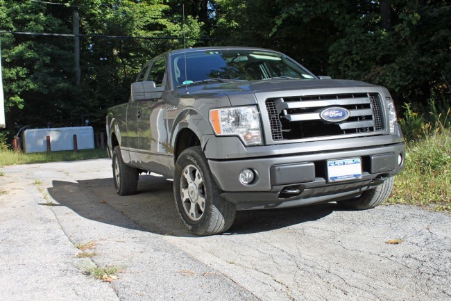
It does not look like much, however, that is about $5,500.00 worth of damage. What you don’t see is the mashed oil cooler and radiator. This happened on my way from one place to another during the early morning hours. I was traveling at about 55 MPH when a deer bolted from the woods and entered the roadway from the right. I did not have time to a break.
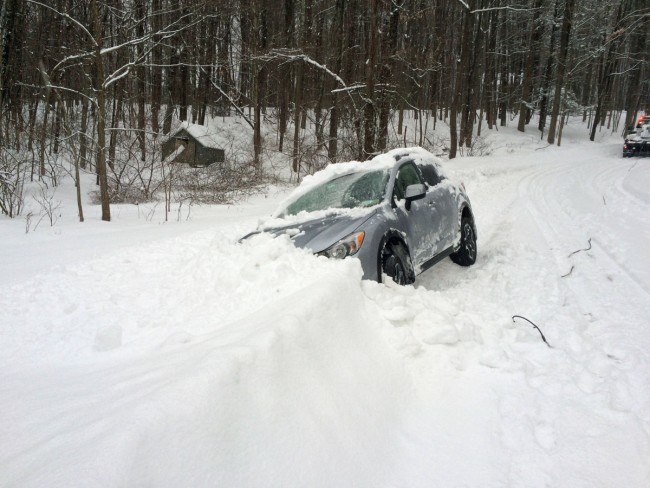
A momentary lapse of attention causes a loss of $80.00. I think I was adjusting the defroster as I was driving down the road when suddenly, I felt the car tilt over to an alarming degree. You can see the tow truck getting ready to pull it out. Fortunately, there was no damage to the vehicle.
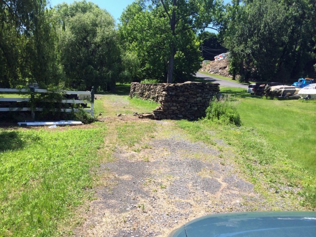
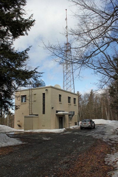
This is on the access road to one of our transmitter sites. The station has a legal right of way through this property, however, the neighbor seems to object. I spoke with him and showed him a copy of our deed, he has since changed plans.
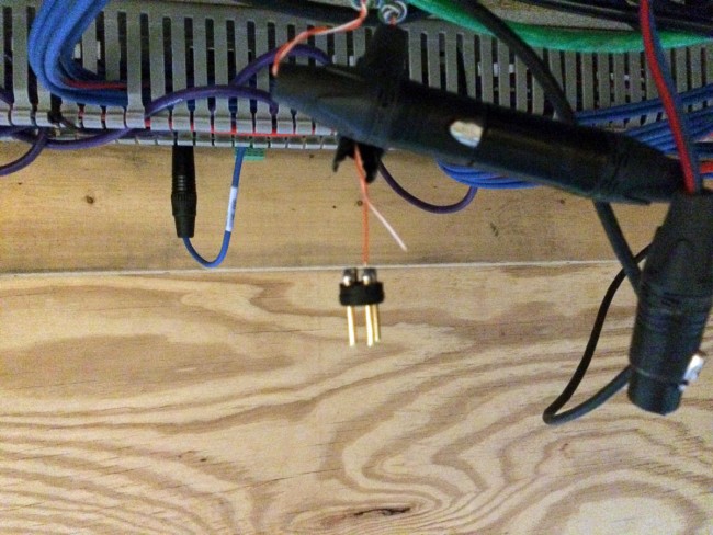
This is the downside of using category cable to make audio connections. The wires are not as rugged as say Belden 8451. This was causing problems because it is at an AM studio/transmitter site.
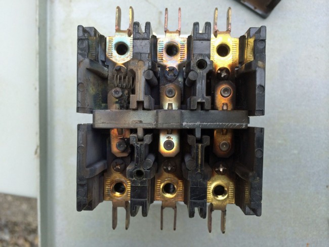
Three-phase, 30 amp, 240-volt contactor installed in a 480-volt system. Lasted a few years, anyway.
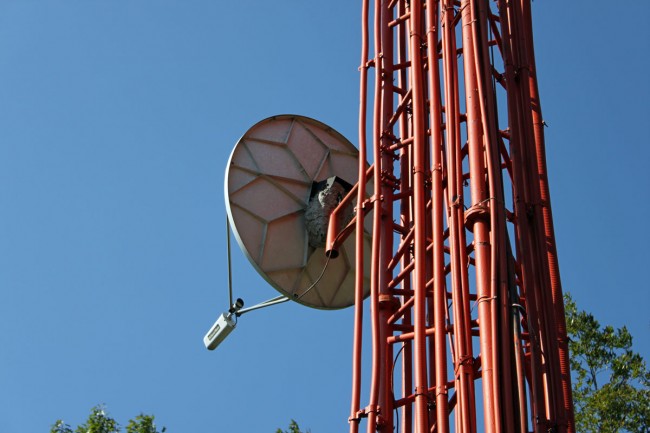
New tenants on one of our towers. This is a white-faced (or bald-faced) hornet’s nest. They are really paper wasps, but that difference aside, these beasts are nasty, aggressive, and have a painful sting. Normally, I am a live-and-let-live kind of person, but in this case, they gotta go.
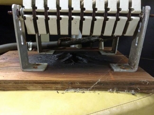
This is at one of our AM client’s site. Somebody, quite some time ago it seems, made this test load for a 1 KW AM transmitter. It is very nice, with carbon ceramic resistors, 50 ohms, and surprisingly little reactance. Then they attached it to this piece of plywood. As one can surmise, the load gets quite hot under full power and full modulation conditions. We remounted this in a cage-type enclosure and bolted it to the cinder block wall.
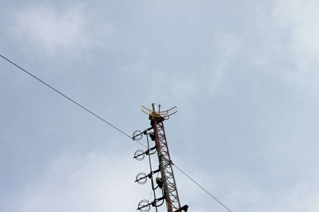
The client at this station is complaining of intermittent STL dropouts and low signal strength at the receiving end. Found this Scala PR-950U antenna mounted for vertical polarization, but the antenna element is horizontally mounted. We’ll call it “vorizontal.”
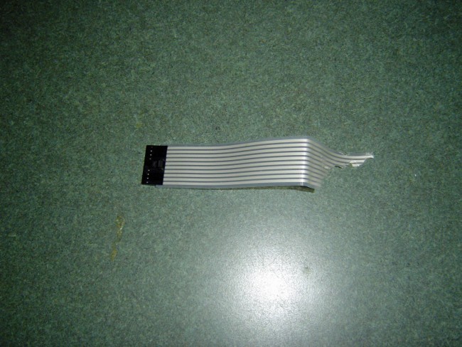
This was discovered during routine maintenance and thankfully not during a power outage. Mice got into the control box of a newish Cummins 135 KW generator and chewed through what looked like a data buss cable. The generator would not run and the cable and control board needed to be replaced.
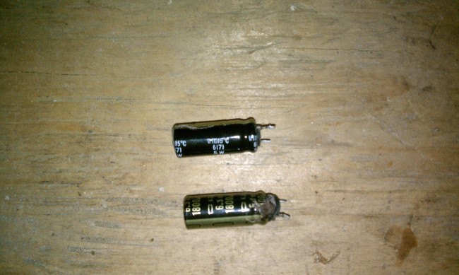
There are more bulging capacitors removed from flat panel monitors.
And so on…