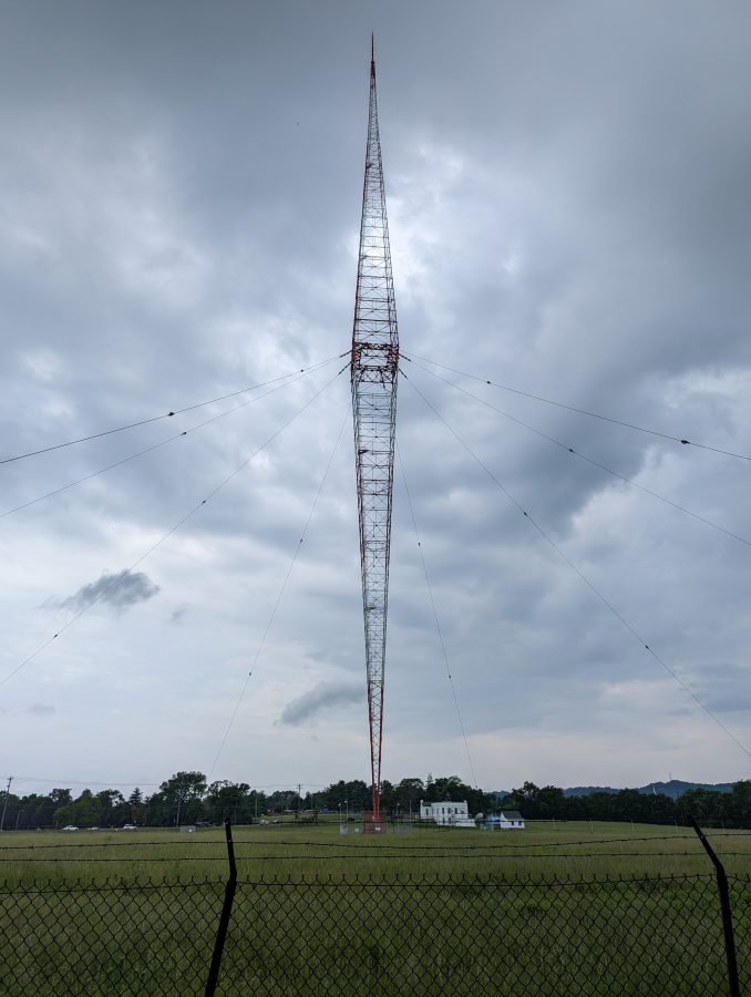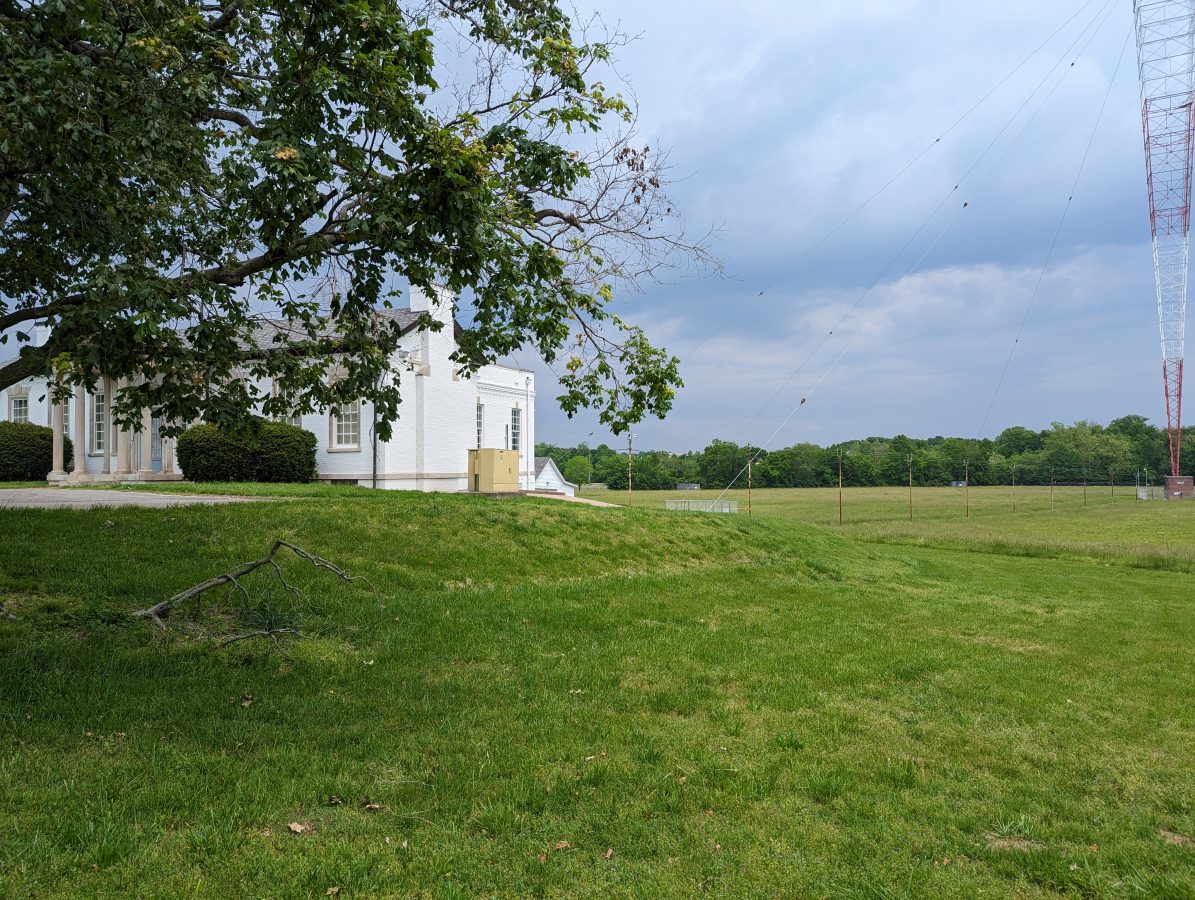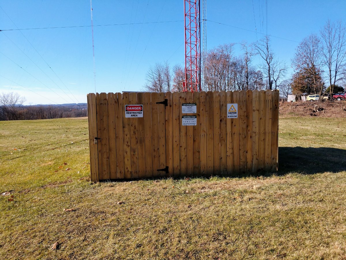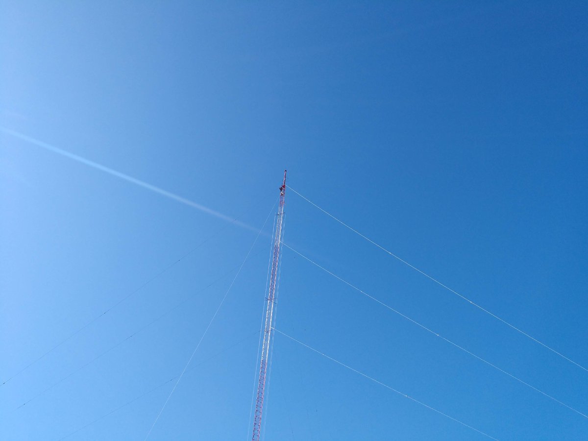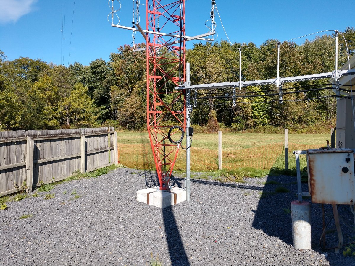
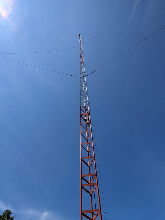
This is the original tower for WKIP, but not the original antenna. It was put up circa 1960 or so and like many towers from that era, has hollow legs. Thus, after 60 years or so, it is deteriorating from the inside out.
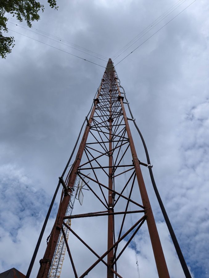
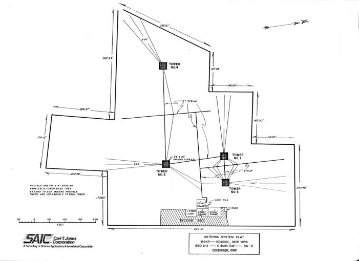
This was part of a two-tower directional array. It is odd that a class C station on 1,450 KHz would have a directional antenna at all. Even stranger still, it was directional daytime, non-directional night, both at 1,000 watts. The reason for such an odd situation; the station was co-owned with WGNY in Newburgh and the daytime coverage contours would have overlapped without a directional array. The taller tower is 215 degrees tall with top loading. During the daytime, the pattern goes to the North and it covered very well.
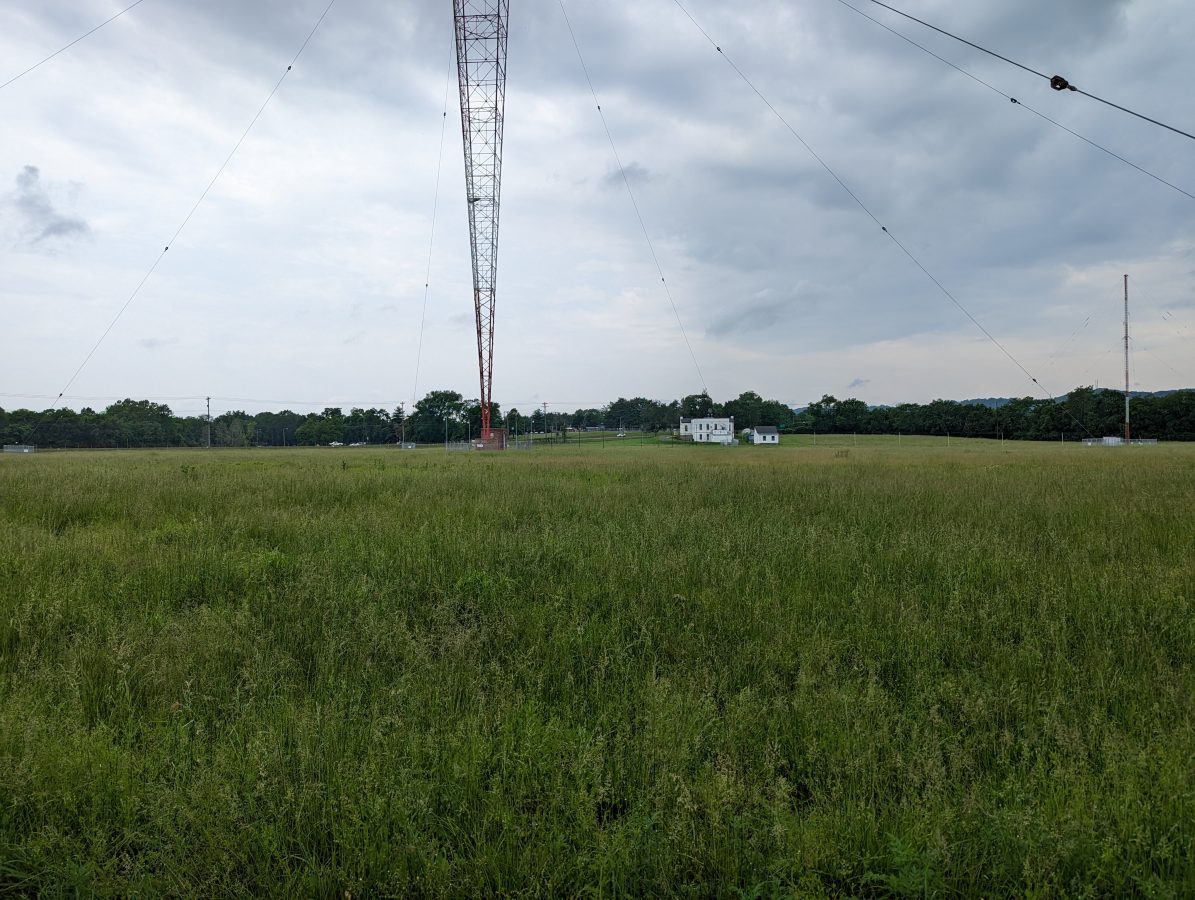
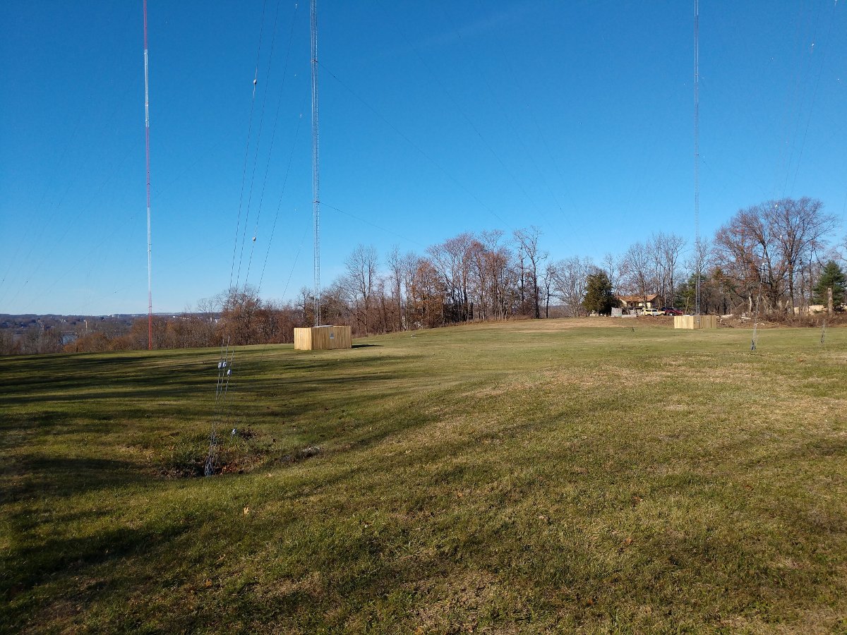
Vertical Bridge, the tower owner, decided it was time to replace the aging structure with a monopole. They are completing the project this summer. Our part is to move WKIP to the shorter tower and put up a temporary FM antenna for the translator. Once the project is completed, WKIP will operate from the shorter tower (which is 85 degrees) permanently, getting rid of the now unnecessary directional antenna on a class C channel. The translator antenna will move back to the monopole, once it is put up.
Problems… Yes, we have a few of those…
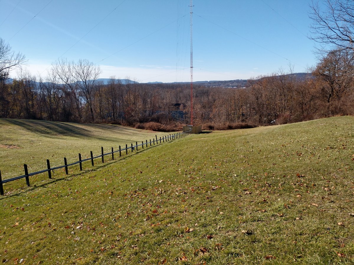
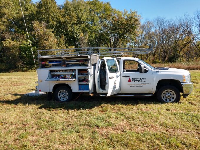
First, the short tower had a broken guy wire. Actually, the guy wire was fine, but the lowest grip connecting to the equalizing plate was rusted through. It is fortunate that this was discovered because the upper guy wire was getting ready to let go too. Northeast Towers was able to replace all of the grips on that set of guy wires and re-tension the tower. They did a full investigation of all of the other anchors prior to any climbing. This is in a swamp, which has flooded several times over the last few years.
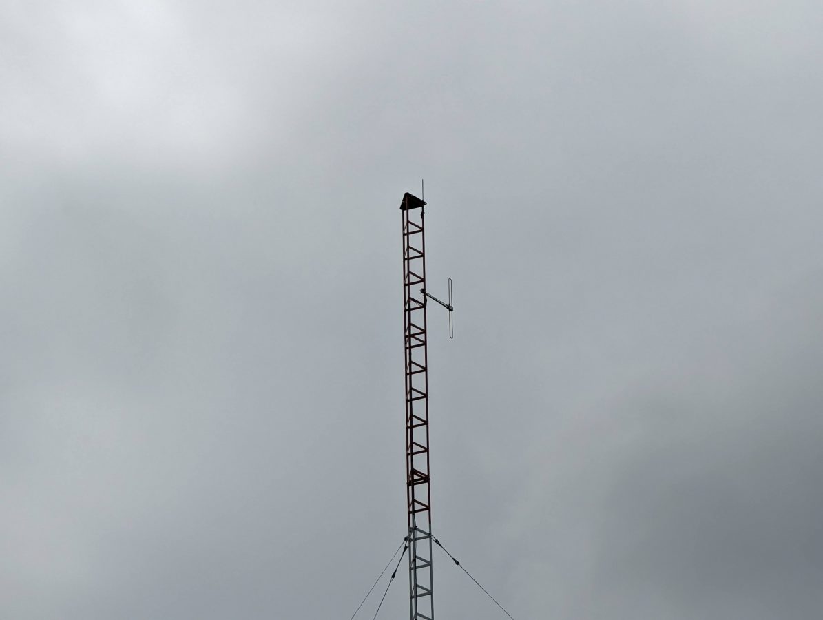
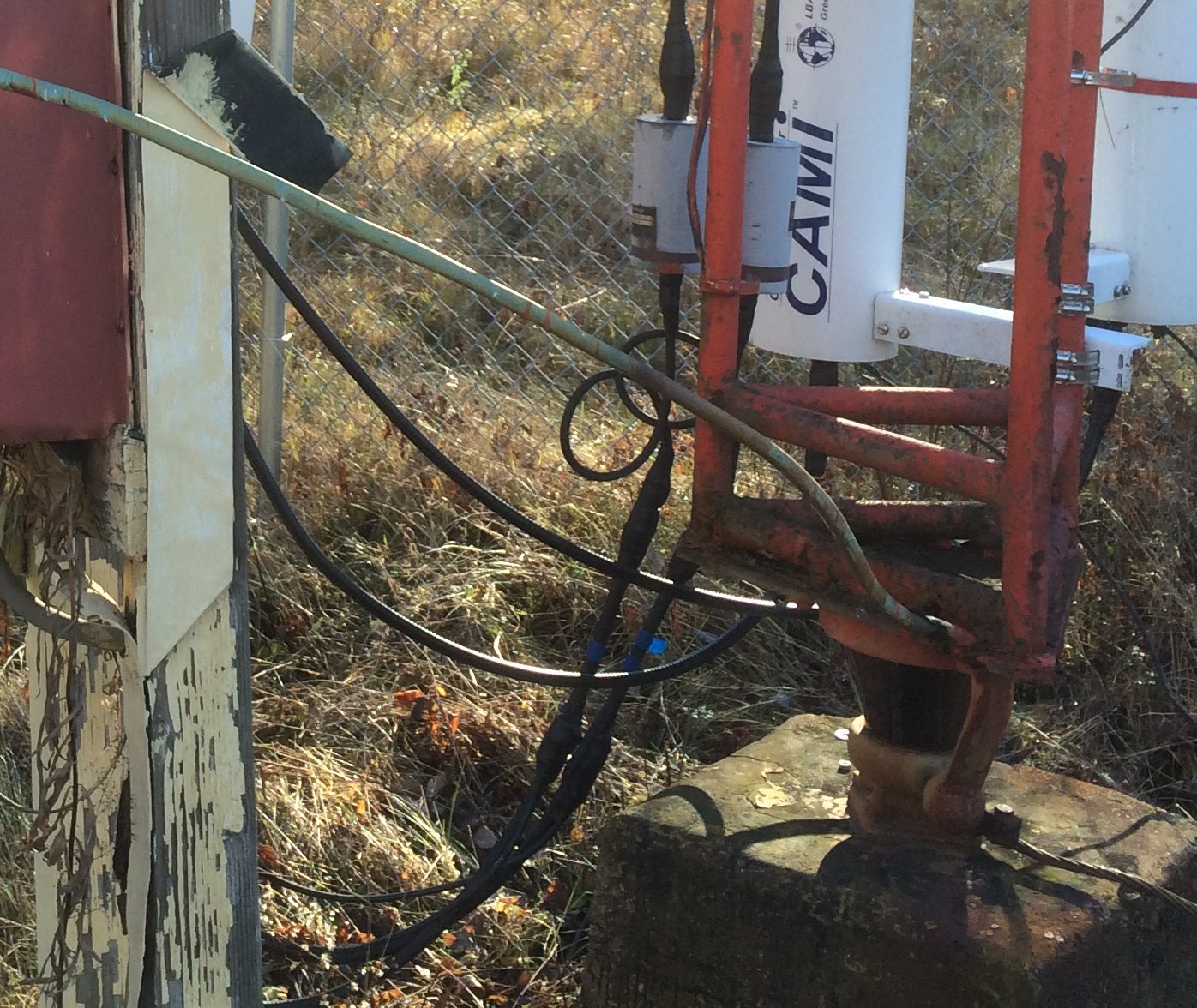
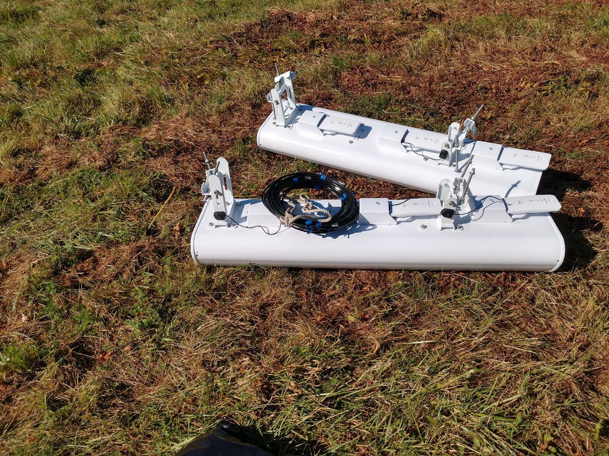
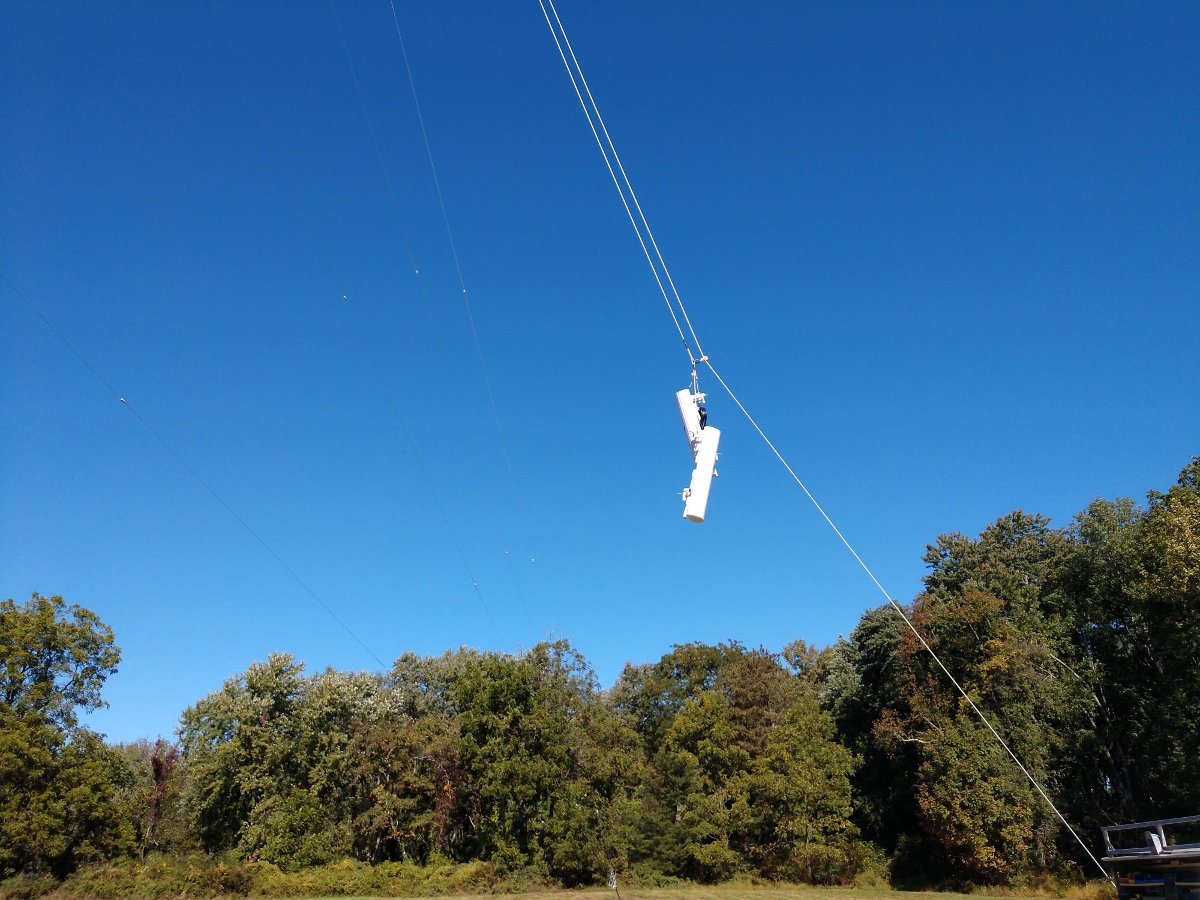
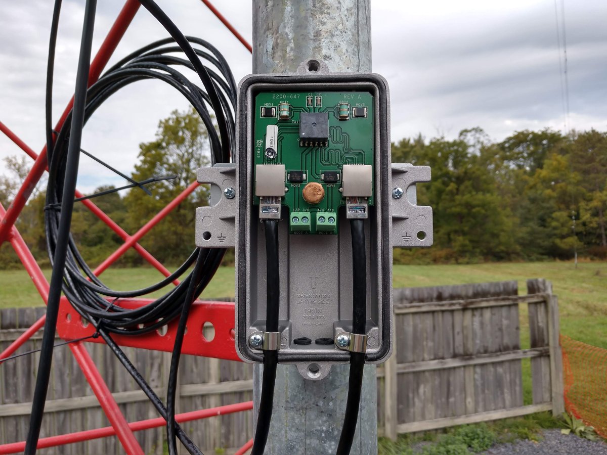
Next, the temporary FM translator antenna was hung on the tower. It was thought that the 3/8 sample line from the old AM sample system could be used as a temporary transmission line for this system. Unfortunately, that line turned out to be 75-ohm cable TV drop line and was not suitable for transmission of VHF. We had about 600 feet of leftover 3/8 sample line (Cablewave FCC 38-50J) from a decommissioned AM site, so we used that instead. It has quite a bit of loss on VHF, however, for temporary use, it will work.
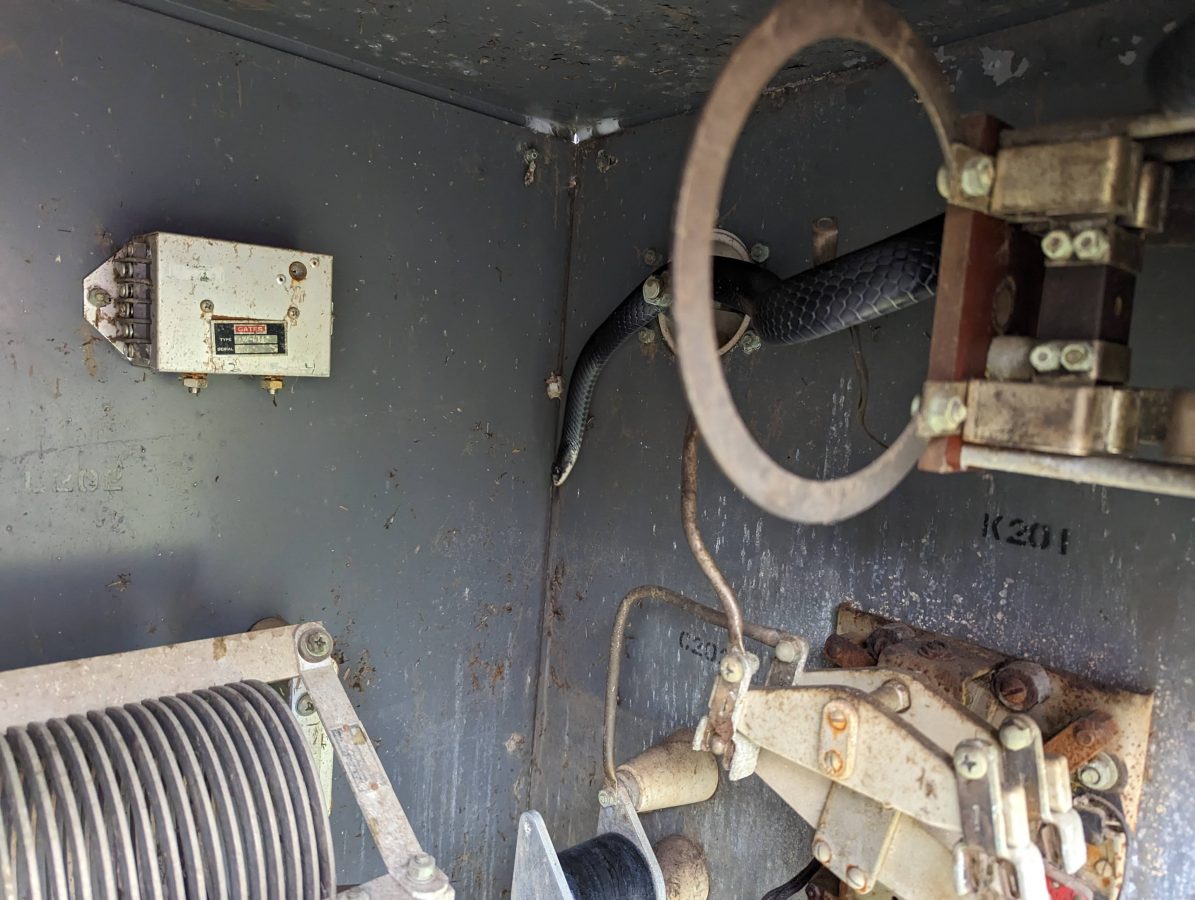
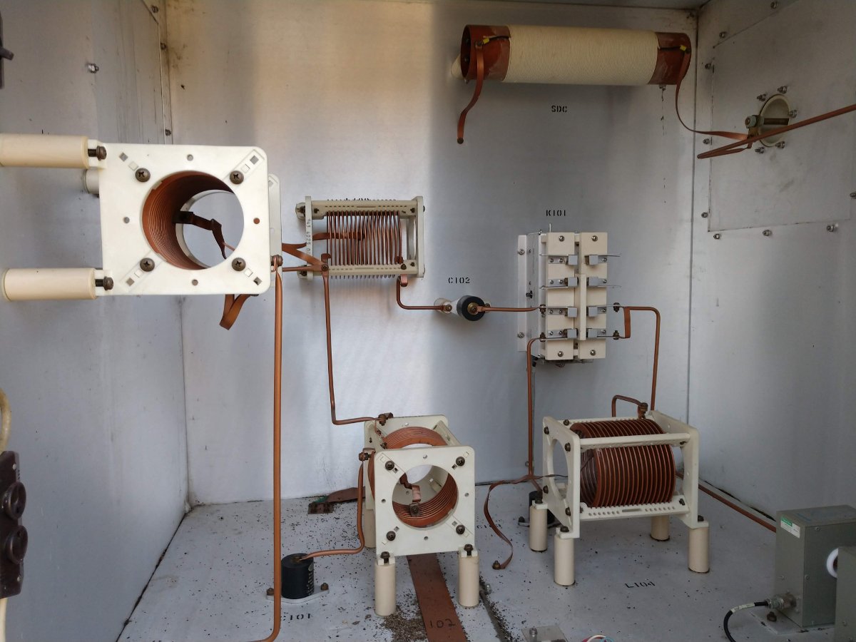
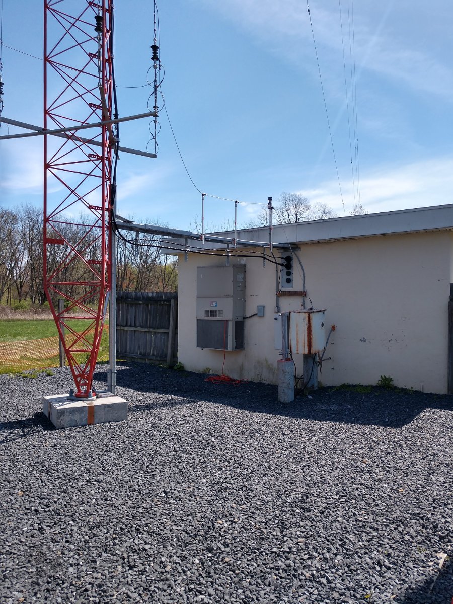
Next, it seems this black rat snake had taken up residence in the ATU cabinet. The bottom of the ATU was full of mouse nests going back many years. One of our employees dutifully cleaned out the mouse nests unknowingly under the watchful eyes of this snake. Only after he was done, did he see the snake coiled up on the disused current meter shunt. There was a mild freakout for several minutes, but the snake left on his own and we got back to work. The black rat snakes are helpful to have around, but perhaps best if he stays outside of the ATU. We will seal up the entryway for the coax, which seems to be where all the critters are coming in.
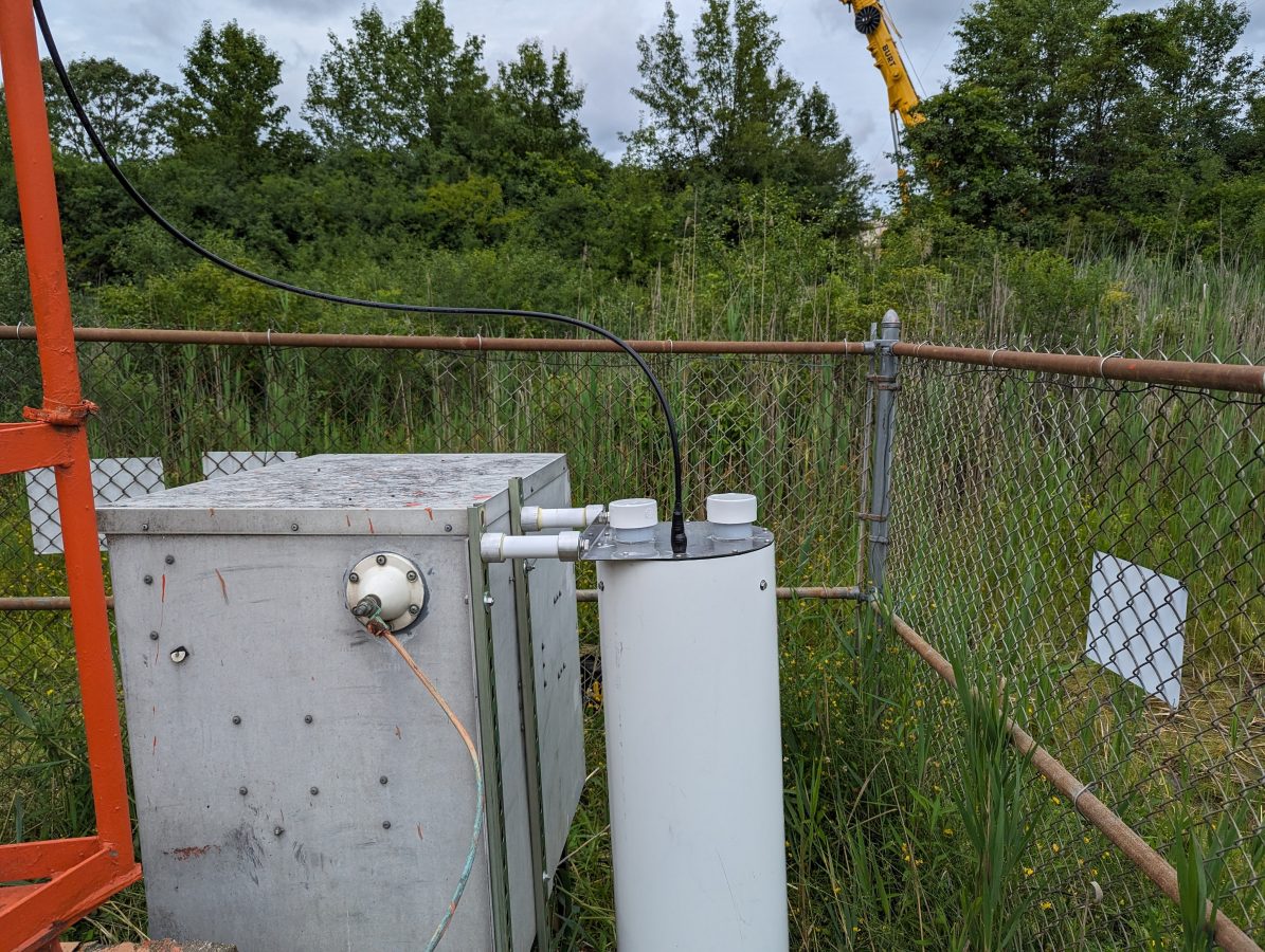
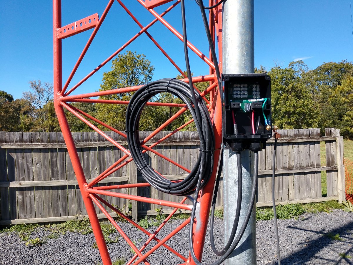
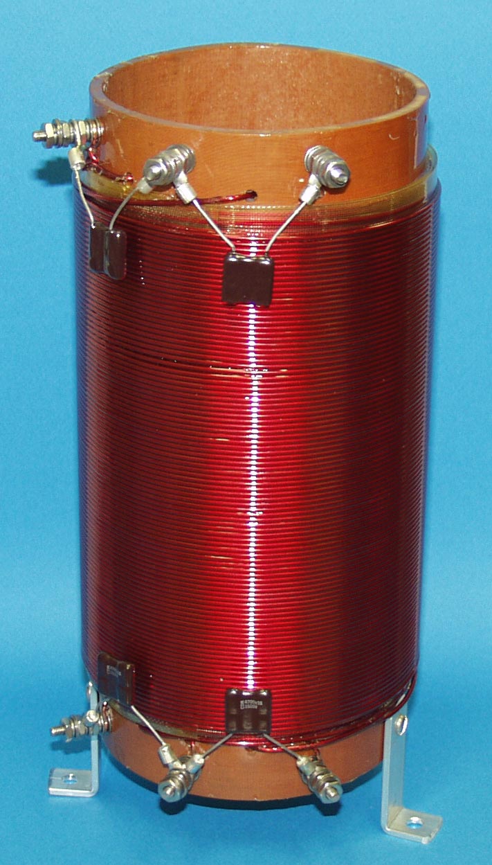
This Kintronic Isocoil was mounted to the back of the ATU with unistrut. Even though this is a temporary installation, I have found that sometimes temporary things can last much longer than anticipated. Besides, it was easier than trying to use pressure treated 4 x 4 lumber.
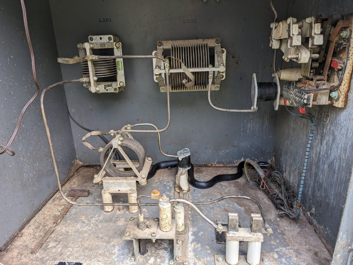
Next, we measured the ATU with the fancy machine (Agilent E5061B network analyzer). In theory, the ATU input should be 50 ohms to match the incoming transmission line. No, instead it was 38 Ohms -j20.
So, a little bit of a retune was required. With the fancy machine, we were able to get it to 52 ohms -j9 or so. This is good enough for now, there will be numerous cranes in the air and the station has an STA to run at 250 watts for the project’s duration. After the new monopole is up, we will measure the base impedance of the tower and tune up the ATU for 50 ohms and then return the station to full power at 1 KW.
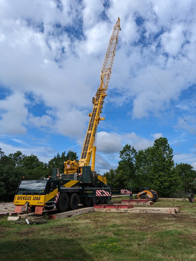
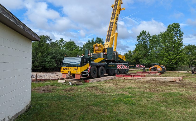
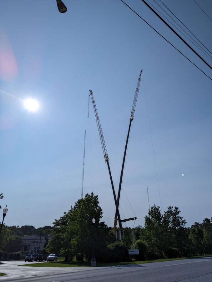
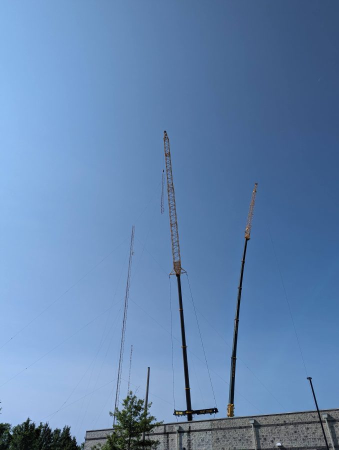
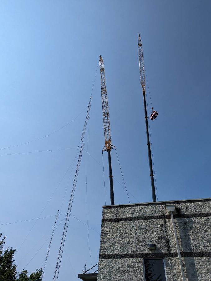
The old tower coming down:
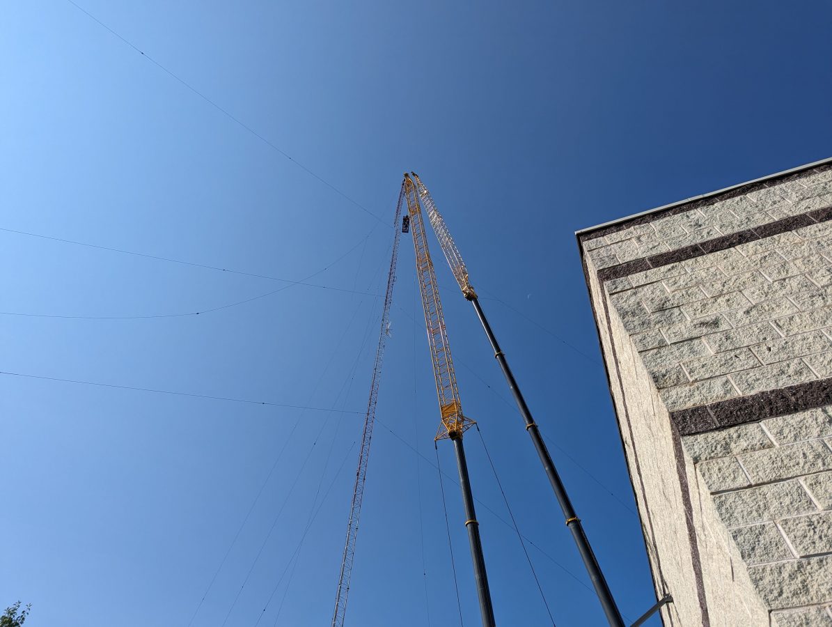
Two cranes were used; one to hold and lower the tower section, the other to lift two tower workers to cut away the sections. The tower was deemed unsafe to climb, therefore it had to be removed like this. It was also unsafe to drop because of the proximity to the studio building and the other tower, which is being retained.
You get the idea. These tower sections and guy wires were cut up and put in a scrap metal dumpster. They will be recycled into something else.
Now, they will work on removing the old tower base and putting up the monopole. Once that is done, we will tune up the AM on the short tower and get it back to full power.