Although not the first station in the area, that honor goes to WGY. In fact, RPI licensed WHAZ in 1923, which makes it the second regional station. Starting on 1430 Khz as WOKO in New York City in 1923, the station made a few stops along the way. One of those was on Mt. Beacon from 1928 until 1930. The original transmitter building is still there, although the tower was taken down in 2005 to make way for the DTV stations that moved in. I always wondered why an FM tower on the top of a mountain had a base insulator.
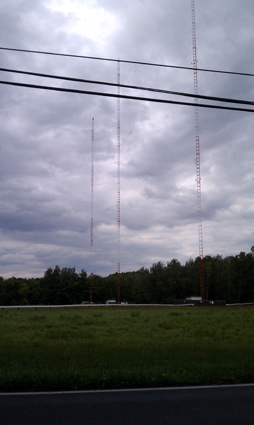
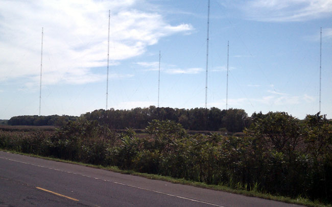
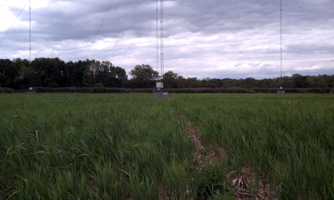
In 1930, WOKO was sold and moved to Albany, NY, becoming the first station licensed to that city. The transmitter site is located off of Kenwood Avenue in the town of Bethlehem, about 4 miles south of downtown Albany. It first signed on with 1 KW, increasing to 5 KW in 1947. This is the original transmitter site, but the towers were redone in the mid-1970s. The towers themselves are 130 electrical degrees (235 feet) tall. Like all AM stations, for years it serviced the community until it was gradually reduced to a satellite repeater, now owned by Disney.
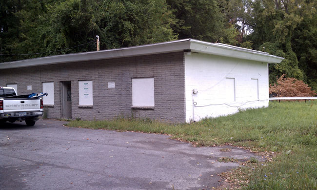
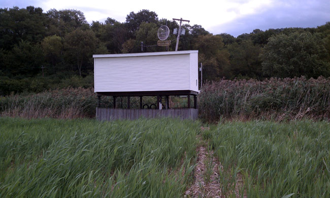
The original transmitter building is in the back, the front was added in the 1970s when the studios and offices colocated with the transmitter. Prior to that, they were in downtown Albany.
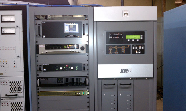
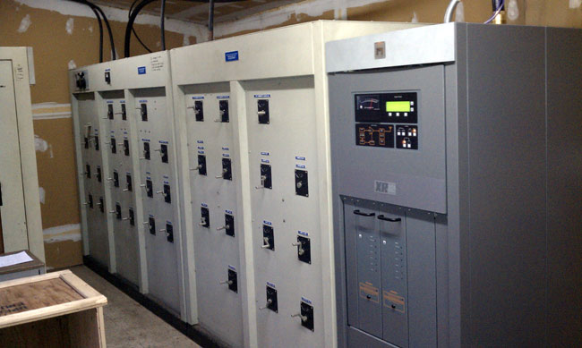
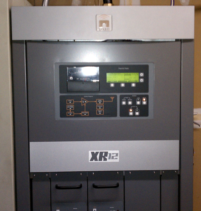
The Harris BC5H transmitter was replaced with a Nautel in 2006. The Harris AM H series transmitter has a pair of transistors on the audio driver board that were unique to that transmitter and no longer manufactured. There are no equivalent replacement parts. Once those transistors fail, the transmitter is done.
I really think that AM could make a comeback, but the following conditions need to be met:
- Kill AM HD radio. Kill it dead.
- Cut away the dead wood. Those stations that are not making money, have not made money and have no hope of ever turning a profit again. Most of these are owned by large consolidators that cannot yet afford to write off the bad investment. More and more will be spun off and given to MMTC and others. If they can make a go of it, good. If not, then the stations will go dark and eventually surrender their licenses. We have one like that around here that basically turns its transmitter on one day a year to avoid license forfeiture. That should stop, either they use it or lose it.
- FM radio will continue to be the investment bank darling, in spite of lower and lower listeners and revenue. This will lead to more and more translators, HD radio, LPFM, and other things being shoehorned into an already crowded band, creating AM-like conditions on the FM band.
- Those that can take on the challenge of an AM station should immediately begin looking at reducing maintenance costs. Directional antennas are money holes, if at all possible, get rid of the DA in favor of a single tower closer to town. Duplexing with another AM is a great way to save money and the costs of building a new tower. Using a taller tower, up to 190 electrical degrees, will daytime signal and reduce the radiation angle (vertical) of the tower, thus permitting better PSSA, PSRA, and or nighttime operation.
- Local programming. Local sports, local politicians, local bands, local church services, local events, etc. Local.
But anyway…