Unbalanced to Balanced Audio

I pulled this out of the published posts and updated it.

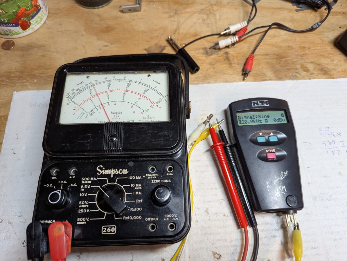
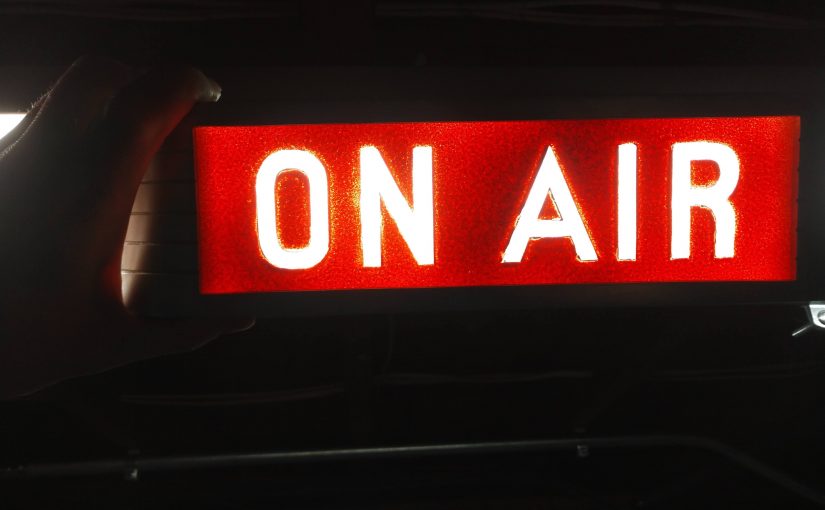
I have been working on updating some wiring at one of our client’s transmitter sites. I noticed that an off air monitor feed was going back to the studio on a Barix box, which is fine. It was being fed from a balanced output of a DA to the unbalanced input on the Barix box. This being at the transmitter site, was susceptible to RF noise. I decided to make a passive audio BALUN.

Balanced to unbalanced audio converter using 10K to 600 ohm transformer

In any case, there are several ways to go from balanced to unbalanced without too much difficulty.  The first way is to wire the shield and Lo together on the unbalanced connector.  This works well with older, transformer input/output gear, so long as the unbalanced cables are kept relatively short.

simple balanced to unbalanced audio connection

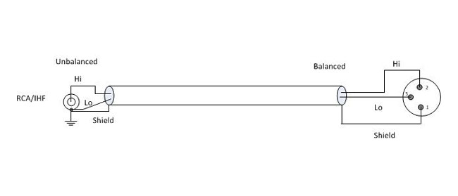
Most modern professional audio equipment has active balanced input/output interfaces, in which case the above circuit will unbalance the audio and decrease the CMRR (Common Mode Rejection Ratio), increasing the chance of noise, buzz, and so on getting into the audio. In this case, the CMRR is about 30 dB at 60 Hz.  Also, newer equipment with active balanced input/output, particularly some brands of sound cards will not like to have the Lo side grounded. In a few instances, this can actually damage the equipment.

A Henry Match Box or something similar can be used.  I have found, however, the active components in such devices can sometimes fail, creating hum, distortion, buzz, or no audio at all.  Well-designed and manufactured passive components (transformers and resistors) will provide excellent performance with little chance of failure.  There are several methods of using transformers to go from balanced to unbalanced or vice versa.

Balanced to unbalanced audio using 1:1 transformer

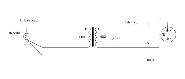
Using a 600:600 ohm transformer is the most common.  Unbalanced audio impedance of consumer-grade electronics can vary anywhere from 270 to 470 ohms or more.  The 10,000-ohm resistor provides constant loading regardless of what the unbalanced impedance.   In this configuration, CMMR (Common-Mode Rejection Ratio) will be 55 dB at 60 Hz, but gradually decreases to about 30 dB for frequencies above 1 KHz.

Balanced to unbalanced audio using a 4:1 transformer

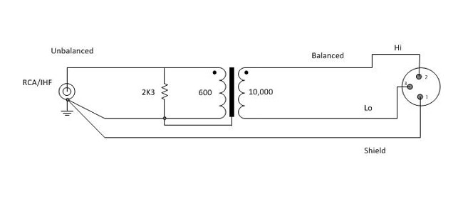
A 600:10,000 ohm transformer will give better performance, as the CMMR will be 120 dB at 60 Hz and 80 dB at 3 KHz, remaining high across the entire audio bandwidth.   The line balancing will be far better for the high-impedance load.  This circuit will have about 12dB attenuation, so plan accordingly.

For best results, use high-quality transformers like Jensen, UTC, or even WE 111C (although they are huge) can be used.  I have found several places where these transformers can be scrounged, DATS cards on the old 7300 series Scientific Atlanta satellite receivers, old modules from PRE consoles, etc.  A simple audio BALUN can be constructed for little cost or effort and sound a whole lot better than doing it the wrong way.

A brief list, there are other types/manufacturers that will work also:

RatioJensenHammondUTCEdcor
1:1 (600:600)JT11E series804, 560GA20, A21, A43PC600/600
4:1 (10K:600)JT10K series560NA35PC10K/600

Keep all unbalanced cable runs as short as possible.  In stereo circuits, phasing is critically important, so pay attention to how the balanced transformer windings are connected.

Device Under Test; THD at 20 KHz

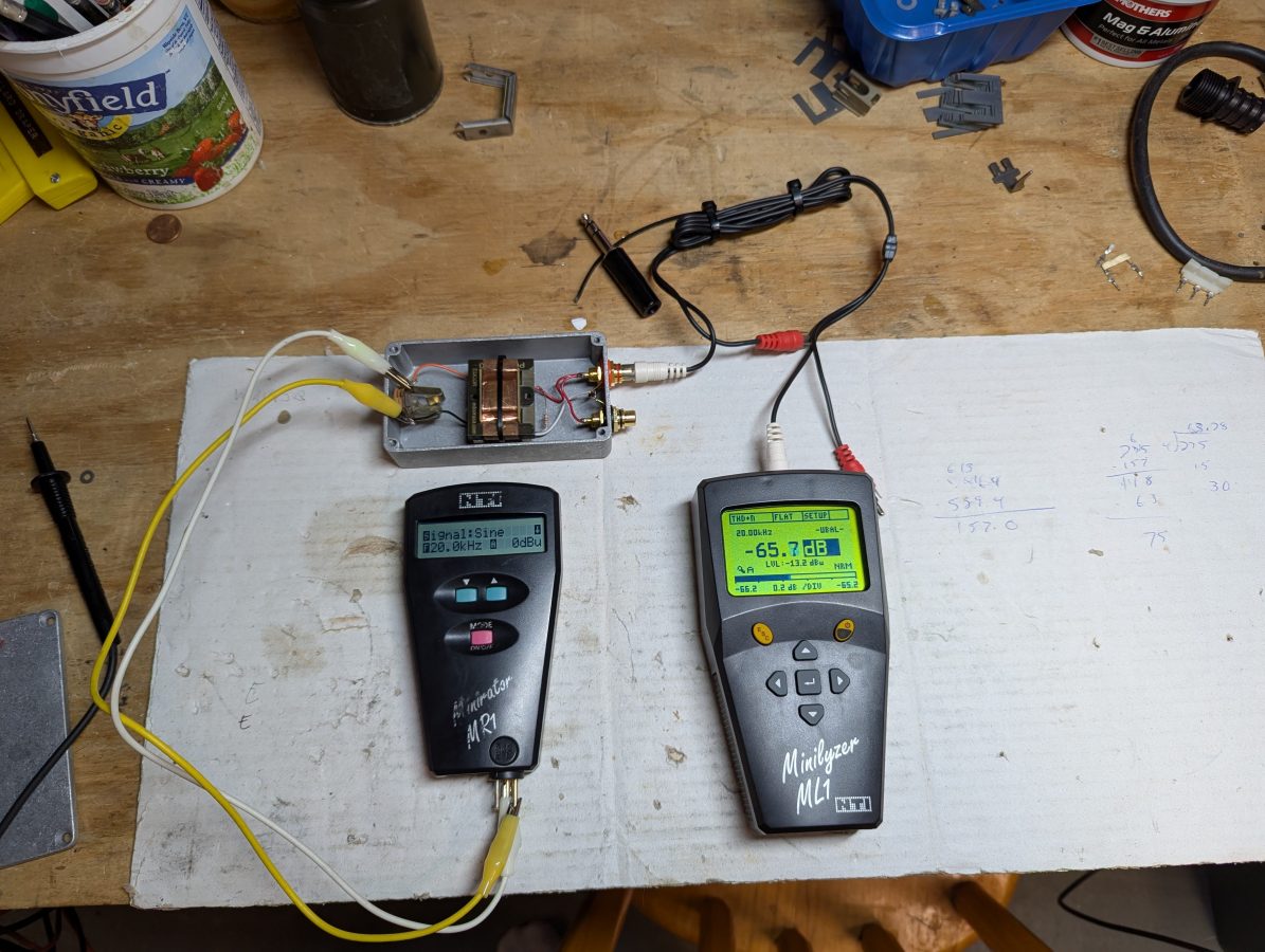
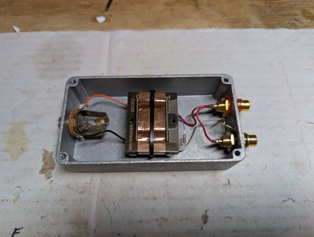
As for cost; I purchased the Edcor PC10K/600 transformer on eBay for $20.00 and the Hammond 1590B Enclosure was about $9.00. The audio jacks and resistor were in the parts drawer. It took about 20 minutes to layout the holes, drill, mount the audio jacks, and solder the jumper wires. I used a tie-base, wire tie, and some Gorilla glue to hold the transformer down. I used a 1/4 inch TRS jack because the enclosure was a little bit too small for an XLR jack. If a stereo pair needed be converted, it would require two of everything.

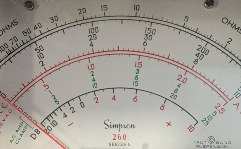
Overall, I fun project. The old Simpson 260 is still accurate!

Checking the accuracy of a Simpson 260 on audio frequencies.

GPS controlled clock based on Raspberry Pi

This is an adjunct to my previous post on creating a Stratum 1 NTP time server with a Raspberry Pi. I finished this project about a year ago, and I have to say it has been running flawlessly since then. I thought that perhaps the inexpensive GPS module designed to work with drones might not hold up. But it has.

Midnight in London

Wouldn’t it be nice to use this time source, not just to set hardware clocks but also display the time in varous places? Yes, yes it would.

Since most of my ideas are not original, I figured a quick internet search may shed some light on how to proceed. Keith, G6NHU did exactly this a year ago or so. His project can be viewed here: https://qso365.co.uk/2023/05/how-to-build-a-shack-clock-using-a-raspberry-pi-and-a-7-touch-display/

As I suspected, with a few more configuration steps, this NTP server can display the time on the native HDMI port as well as create a simple web page available on the LAN for any computer to access with a web browser. The web server is Lighttpd, which is a low CPU load, low memory demon, perfect for an older Raspberry Pi 3.

The display I chose is a 7-inch 16×9 non-touch purchased from Amazon for $33.99: https://www.amazon.com/gp/product/B0BGXB2Y67/ (not an affiliate link)

When I created the NTP server last year, I named it ntpserver. The unit runs headless (no keyboard or monitor) so I use ssh to get into the command line. Thus, the first command is:

ssh ntpserver@192.168.1.200

Once in, always do an update:

sudo apt-get update
sudo apt-get upgrade -y

The following programs need to be added to the Pi:

sudo apt install xorg openbox xserver-xorg xinit unclutter lighttpd -y

If the OS is off the shelf Raspian, then Chromium should already be installed, but if not, then add it:

sudo apt install chromium-browser -y

Once that is done, some things need to be configured. Using whatever text editor you like the xserver so that anyone can access it. Open the Xwrapper file:

sudo nano /etc/X11/Xwrapper.config

Then add line:

allowed_users=anybody

Exit and save. Next open the xserverrc file:

sudo nano /home/ntpserver/.xserverrc

Add the following:

#!/bin/sh
#Start the X server session with no power management so the display never sleeps
exec /usr/bin/X -s 0 -dpms -nolisten tcp "$@"

Exit and save. Next open the xsession file:

sudo nano /home/ntpserver/.xsession

Add the following:

#!/bin/sh
#Start Chromium at startup
chromium-browser --start-fullscreen --window-size=800,480 --disable-infobars --noerrdialogs --incognito --kiosk http://localhost

Exit and save. Note the display size can be configured to any screen resolution. This affects the HDMI port, not the web page. The 7-inch Raspberry Pi monitor that I purchased from Amazon has an 800 x 480 screen resolution. If you are using a different screen resolution, change as needed. Next open the clock.service file (it will be created when you save the file):

sudo nano /etc/systemd/system/clock.service

Add the following:

[Unit]
Description=Clock
After=network-online.target
DefaultDependencies=no

[Service]
User=clock
ExecStart=/usr/bin/startx
Restart=always
RestartSec=10

[Install]
WantedBy=multi-user.target

Exit and save.

The web page that will be displayed on the HDMI port as well as served to local hosts on the LAN is a java script page. It was originally developed by Nayuki: https://www.nayuki.io/page/full-screen-clock-javascript You can download whatever format you like from that site (I copied the page source) or you can download a 24-hour format from Keith’s site:

cd /var/www/html
sudo wget https://qsl.net/g6nhu/clock/index.html

The colors can be edited:

sudo nano /var/www/html/index.html

The background, foreground, and font type can be changed as desired.

Next start the clock service and reboot:

sudo systemctl enable clock
sudo systemctl start clock
sudo reboot now

Here is a quick video of the web page on my desktop computer. I have the GPS monitor from the ntpserver up and running in the left upper corner. That shows the GPS data going into the Raspberry Pi from the serial port along with some scratchy WWV audio. The actual clock sync is from the 1PPS output of the GPS module.

I could see this being used as an inexpensive master clock system somewhere. With an HDMI splitter (or a better name would be Distribution Amp), this could be sent to many locations.

Now all I need to do is figure out how to get a GPS synced 10 MHz output capable of driving multiple devices.

Salvaged classic equipment

During the early days of COVID, we were engaged to move a studio out of an old location in a hurry. There had been a long-simmering dispute with the landlord, who finally changed the locks (illegally), but then gave 30 days’ notice, and so on. Regardless, we were building a new studio a few blocks away and were told to take anything usable, which we did.

I noticed the old RCA on-air light for one of the studios and the owner said he’d like to have that installed at the new place. There were two other ones that were not working. In total, we ended up with three of these:

RCA M-11717 on-air warning light

As far as I can tell, they dated from around 1960 and were filthy. Sixty years of dust, dirt, cigarette smoke, etc needed to be scrubbed off of them.

On-air lights cleaned

The original light bulb was a bi-pin 110-volt incandescent lamp. Over the years, the sockets became brittle and fell apart.

Rather than trying to source replacements for the lamp holder, I figured it was easier to install a 12 VDC LED module. That way this would become a low-voltage device and the LED module should last for as long as the studio is in use.

RCA M-11717 on-air light updated
Bench Test
On-air lights install

I took the two best units and installed them in the new studio. One of those units needed minor touchups to the black paint. The third unit’s paint was in bad shape. I opted to strip off all the black paint and repaint it, this time with red.