Fixing small problems

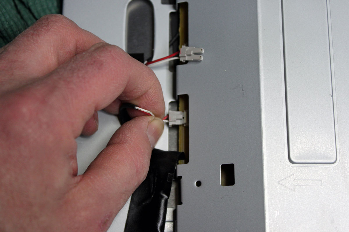
This happened recently at an AM station we were doing work for. It seems the modulation monitor was not working when connected to the backup transmitter. A quick check of the RG-58 coax showed that I had the correct cable plugged into the monitor selector relay.  Another check with an ohm meter showed the cable was okay.  Then I looked at the connector on the monitor port of the transmitter and saw this:

BNC connector pin  improperly located
BNC connector pin improperly located

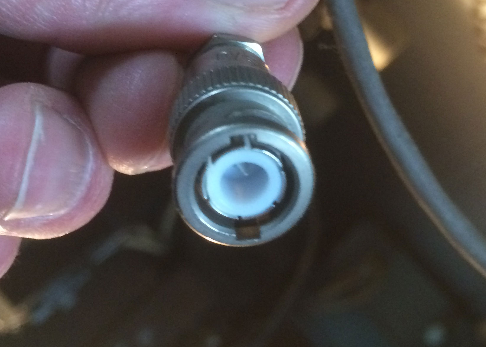
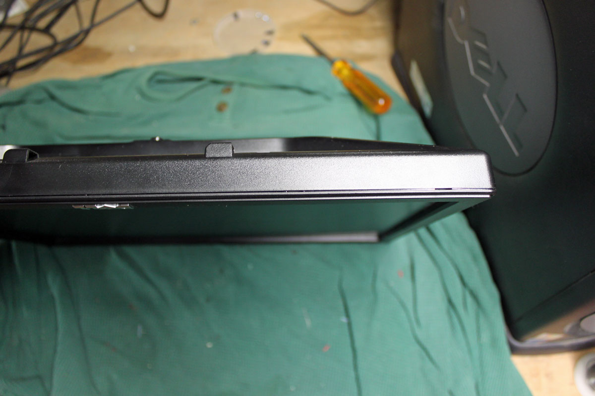
Looks like the pin is too far back in the connector. This is an old-style BNC connector with solder in center pin:

BNC connector center pin
BNC connector solder type center pin

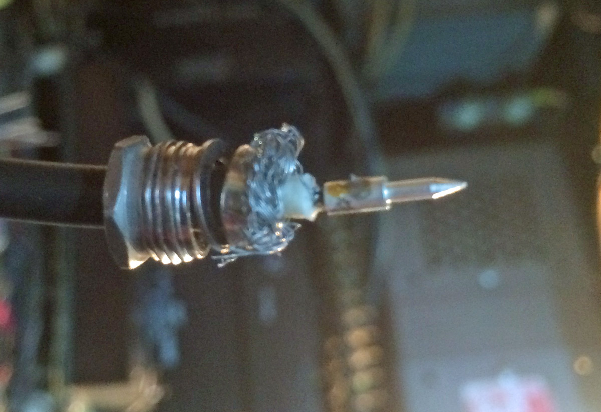
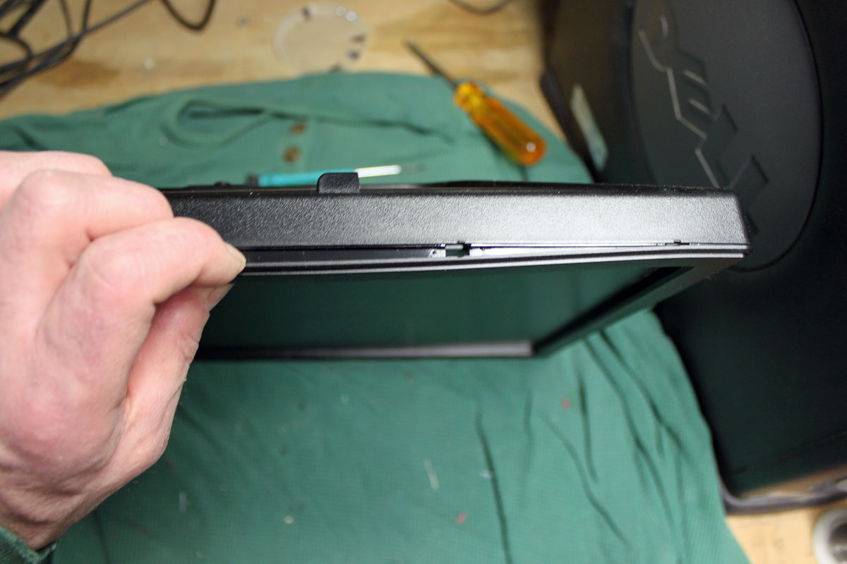
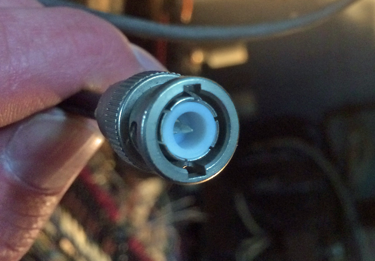
The center pin has a blob of solder on it, preventing it from seating properly in the connector body. I could have lopped it off and applied a new crimp on connector, but my crimp tool was in the car. I didn’t feel like walking all the way through the studio building, out into the parking lot and getting it. Therefore, I used a file and filed off the solder blob then reassembled the connector:

BNC connector
BNC connector

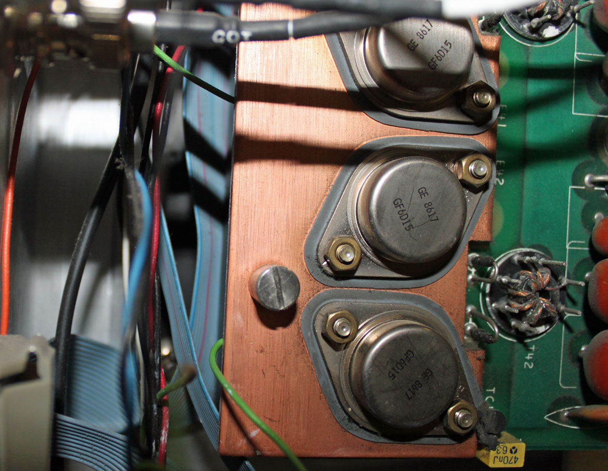
The transmitter was installed in 1986, I think the connector had been like that for a long time.

It may seem like a small detail to have the modulation monitor working on the backup transmitter, however, the modulation monitor is also the air monitor for the studio.  Switching to the backup transmitter but not having a working air monitor would likely have caused confusion and the staff might think they are still off the air.  I know in this day and age, a lot of station do not even have backup transmitters, but when something is available, it should work correctly.

I like my cool network analyzer and all that, but sometimes it is the Mark 1, Mod 0 eyeball that gets the job done.

Repairing the Nautel VS2.5 transmitter

The newish Nautel VS2.5 transmitter installed at WJJR had an RF module failure. This particular model transmitter does not have slide-in RF modules as other Nautel transmitters do.  To fix this transmitter, it has to be pulled out of the rack, flipped over, and opened from the bottom. The module replacement is very straightforward, there are five solder pads that connect to wires carrying the input, output, power supply, and bias voltages.

Nautel VS2.5 transmitter RF modules and combiner

The troubleshooting guide gives good instructions on how to check the PA MOSFETS with a DVM. I found that 1/2 of the device in PA1 was bad:

Schematic Diagram, NAPA31

All in all, not a very hard repair. This was under warranty, so a replacement RF pallet was sent to the station without charge. The problem is more about where the transmitter is located:

Killington Mountain, Killington, VT

Killington Peak is the second tallest mountain in Vermont, topping out at 4,235 feet (1,291 meters). In the winter, one can take the chair lift to the top. In the summer, the road is drivable with a four-wheel drive. In those in between months, access to the top can be very tricky at best. We had a pretty wet spring this year, so the roads up the mountain are just now becoming passable for vehicles.

Even after reaching the parking lot, there is still a 10 minute walk to the peak, another 200 or so feet up a steep, rocky trail.

Further complicating things, this transmitter is wedged into this little shack, which holds; a BE FM3.5A transmitter (defunct WJJR), a Harris HT3 transmitter (WZRT), an ERI combiner, two racks of equipment (STLs, Exciters, remote controls, etc) a backup QEI transmitter, an Onan generator transfer switch:

Killington Peak fire tower, WJJR WZRT transmitter building

Both stations run into this ERI half-wave spaced antenna:

WJJR WZRT ERI antenna

It is very tight in this transmitter room. There is a new tower on Killington Peak, which is still under construction. At some point, the plan is to move into the larger building next to the new tower.

Killington Peak tower

On a clear day, the view from the top is spectacular. On this day, the peak was in the clouds, so not so much:

Killington Peak view

It is a great site, the HAAT is 2590 feet (790 meters) and the stations carry forever on relatively low power outputs.

Repairing a computer monitor

I have seen many a Dell LCD computer monitor go south for want of a $0.50 part. Dell must have gotten a hold of a bad batch of capacitors because almost invariably, the problem is with the power supply capacitors for the backlight. The symptoms are; the monitor goes very dim and can only be read when shining a light on it, or the power button flashes green.

A new Dell 19-inch (E1914H) monitor runs about $90.00 – 110.00.  I can repair a defective unit in about 20-30 minutes or so, which makes it worthwhile for the client.  When repairing equipment, the cost of labor and parts balanced across the cost of new equipment should be a prime consideration.  Sometimes, it is simply not worth the time to repair something.  In others, like this instance, it makes sense as long as the repair is simple.

This is a Dell E198FPf LCD monitor.  After the initial diagnosis:

Dell E198FPf LCD monitor back lighting problem
Dell E198FPf LCD monitor backlighting problem

The first step is to remove the stand and the four screws behind the stand bracket.

LCD monitor stand removed

The hardest thing about this repair is getting the bezel off.  Dell uses a bezel around the monitor face that uses little plastic clips to hold it in place.  To get the bezel off, one needs to press the clips toward the center of the monitor while lifting it up.  It requires the careful application of force.

Dell E198FPf monitor bezel

I start on the bottom and use a small screwdriver in one of the slots to get it started. I start on the bottom because if the plastic gets a little marred, no one will see it when the repair is finished.  Once the first clip is released, then the others and be released by twisting the bezel carefully toward the center of the monitor while lifting.

Monitor bezel removal
LCD monitor bezel removal

Once the bezel is removed, the wiring needs to be disconnected. This consists of the backlight, the data buss, and sometimes the on/off switches, which are mounted on the bezel.

LCD monitor backlight connector
LCD monitor data buss
LCD monitor data buss connector

After all the wiring is removed, there are either two or four screws that hold the power supply to the monitor screen.

LCD monitor power supply bracket  screws
LCD monitor power supply bracket screws

Finally, the power supply board is exposed.  Depending on the model of the monitor, the hex head screws that hold the VGA connector may need to be taken off.  Sometimes not.

LCD monitor power supply

Removing the screws on the back of the power supply board exposes the capacitors and other components.

LCD monitor bulging capacitors

And the culprit is discovered. These two bulging capacitors are causing the LCD monitor backlight power supply shut down making the monitor unusable. The larger one is a 1000 uF 25 volt and the smaller is 680 uF 25 volt. I replaced both with in kind 35 volt units.  I also took the liberty of replacing the rest of the electrolytics on the power supply board (total of five additional capacitors).  While the unit is disassembled, it is far easier to replace all the $0.50 components than to do it one at a time over the next few years as each fails.  This monitor should be good for another 5 years of service at least.  These values vary somewhat from monitor to monitor.  Also, if only repairing one or two monitors, the parts can be obtained at Radio Shack for $1.99 each.

It is a good way to regenerate equipment, even if they are set aside as spares.

Oh damn, La cuarta parte

Today there will be a quiz.  Ready?  Look at this picture and see if you can spot the problem:

Problem with Harris SX2.5A transmitter

If you said “Hey, that green wire seems a little odd; it disappears behind the heat sink next to that screw then reappears again at the top,” you are correct.  What really sucks is the green wire is the transmitter off connection to the remote control.  So, when the PA board was secured to the heat sink, the wire was trapped between the board and the heat sink.  Since the components were cold, they did not pinch through the insulation right away, no.  Rather, after the transmitter ran for several hours at full power, it got hot enough to displace the wire insulation and cause a short.  Doh!  The transmitter is off and it won’t come back on!

This is a picture of the wire after it was removed:

Pinched wire
Pinched wire

Haste makes waste.  Unfortunately, it was someone else’s haste that ruined my Saturday afternoon when I was supposed to be taking my son to little league practice.  I am sure that some not-so-kind words will be exchanged very soon.

Always double-check your work.