It’s the middle of the night and the phone is ringing. That is never good. The transmitter is off the air. You call the remote control and try to put the main transmitter back on the air. No good. The backup comes up, no problem. Shaking off the sluggishness, you get dressed and head out the door. The transmitter is about 30 miles away, but it’s in the middle of the night, so there is no traffic. While driving, you are thinking of all the things that could be wrong. The blower motor was sounding a little loud last trip. The exciter has some reflected power. The PA tube is two and a half years old.
Upon arrival, there are several overload lights lit, including the driver’s plate. An investigation is in order. You turn everything off and open the doors. The trouble seems to be a bad IPA power supply. There are spares on the parts shelf, so you put one in. Put the transmitter into the dummy load. You turn on the filament and the transmitter comes to life again. Reset the overloads.
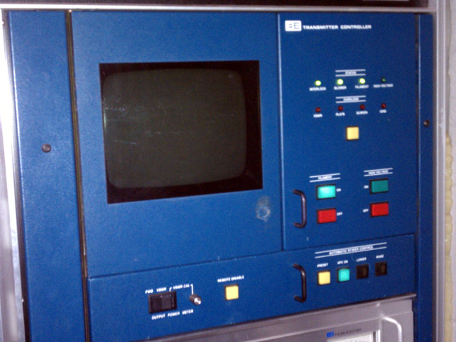
Broadcast Electronics FM35A transmitter ready to be turned on
Now you are standing there looking at the plate-on button. Was it really only the IPA or was that just a symptom? Was there something else that took out the IPA power supply? What will happen when I press the plate-on button? Will it come on normally or go BANG! I hate BANG! By the way, my tradition in a situation like this, if on a mountain top somewhere, I go outside and pee. I give the situation one more run through the mental checklist, then come back inside and press the button.
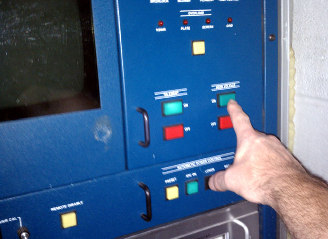
Broadcast Electronics FM35A transmitter high voltage on button
Please excuse the blurry picture, it is hard to take a picture of yourself turning on a transmitter…
Gone is the day when the radio station engineer had to troubleshoot down to the component level, often crawling in and out of transmitters to get at the suspected part. I for one, spent many a long night at a transmitter site chasing some weird combination of symptoms down to the $0.34 1N914 diode in the directional coupler (see previous post about the MW-50).
It is a skill set now mostly confined to manufacturers’ repair departments, for which they charge a pretty penny. Nowadays, the technician simply slides out one module or circuit card and slides in another. If that doesn’t fix it, panic ensues. I know of several class C FM radio stations that are now relying on the computer guy to fix transmitters, because, you know, it’s cheaper.
To be fair, most engineers are contractors and many of those simply do not have the time to troubleshoot to the component level. So, they ship everything back to the factory and then pass the cost on to their client.
Then of course, most circuit boards these days are surface mount systems, which are hard to work on if you don’t have the right tools. Normally an expensive temperature-controlled soldering station is required, as well as a magnifying glass.
All of these things combine to make circuit board work something to be outsourced. Unfortunately, a night spent troubleshooting was often a great learning experience. I have done some of my best work when my back was up against a wall and I was out of options.
I make the attempt to fix things locally unless the transmitter or other item is under warranty or not having a spare/attempting to troubleshoot will take the station off the air. I think it is important to keep abreast of technology and keep my troubleshooting skills up to par. Besides, I find it gratifying that at least I can still fix things.
We have a Harris Z5-CD transmitter for one of our FM stations. Brand H is not my preferred make, however, it was already installed when we bought the station, so I have to live with it.
This particular site gets hit by lightning strikes often. Normally, it does not affect anything until the transmitter gets turned off for maintenance. Then, almost invariably, when turning the transmitter back on one of the modules will fail. Most often this is manifest when one of the two power supplies shut down causing the transmitter to run no more than 20% power.
The way this is troubleshot is to slide each module out and turn the transmitter back on. When the power supply stays on, the bad module has been located. A confirmation test is to check the MOSFET for a short circuit between Drain and Source. This short circuit condition puts a direct short on the power supply causing it to crowbar and turn off.
So, once the bad module has been located, and the spare module is installed in the transmitter, then what? Most engineers call Harris and ship the module back for repair. Most engineers don’t want to mess with unsoldering a surface mount MOSFET and soldering a new one in. I find it moderately entertaining to fix things myself, so I do not do what most engineers do.
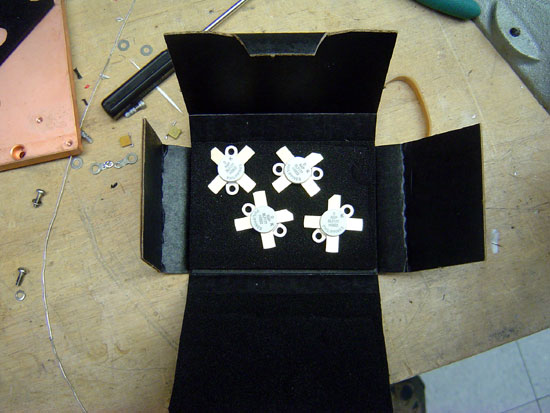
NXP BLF177 MOSFETS
The MOSFET in this particular module is the BLF177, made by NXP. Harris will sell you one for quite a bit of money. You can also buy one from Mouser for about half the cost.
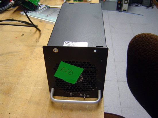
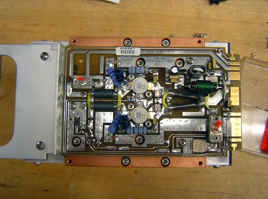
Harris FM Z series transmitter PA module with cover removed
Once the parts are obtained, the worst part of the entire job is unsoldering the old MOSFET. This takes some patience and skill. What I found works best is to melt some solder on the foil leads and get them good and hot. Since this MOSFET is already destroyed, we don’t have to worry about heat, etc. The one thing you do not want to do it actually break the MOSFET open. That is because it contains beryllium oxide, a known carcinogen. Once all the solder is liquid, carefully pry the foil up with a small screwdriver. There are several components that have to be moved to work on this.
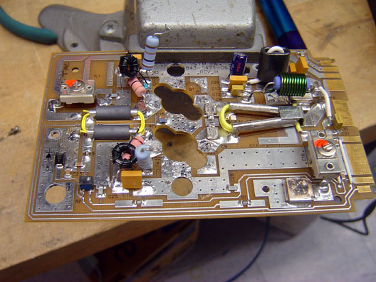
Harris Z series PA module with MOSFETS removed
After the old MOSFET is removed, clean up the solder pad with a solder pump and solder wick. I like to use a little liquid flux on the solder wick, it makes things go faster.
Once all the old solder is cleaned off the solder pads, I brush a light coat of liquid flux in the pad. Again, this makes things go faster.
Harris Z series FM transmitter module new MOSFETs waiting to be soldered
The new MOSFETS are very sensitive to static discharge, so I always use a static drain wristband when handling them. I place both MOSFETs onto the circuit board. I then solder them on using as little heat as possible from the soldering iron. Again, the MOSFETs are sensitive to heat and one can easily be destroyed if it gets too hot.
Harris Z FM series PA module repaired
This is the module with the new MOSFETs soldered in. I use defluxing compound to remove all the extra flux. Once it cools off, I test the new module with a DVM:
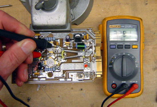
Harris Z series FM PA circuit board under test, resistance is 3.3 Mohm
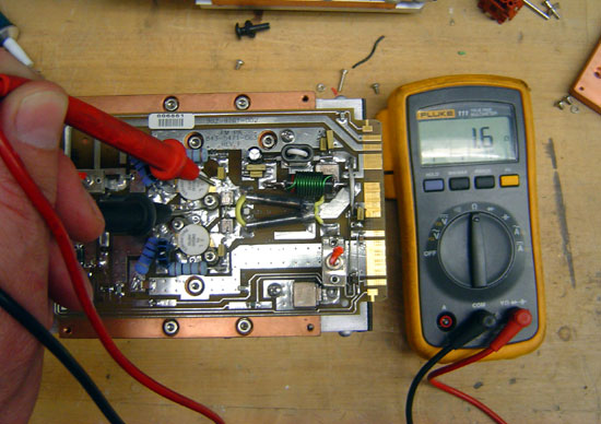
If the MOSFETS are good, they will have an internal resistance of around 3.3 MΩ. If the module is bad the MOSFETS will read only a few ohms if shorted:
Harris Z series FM PA module under test, DVM reads 1.6 ohms
That is how you do it. I think Harris charges $775.00 per module to repair. I fixed this one for $240.00, but that is not the reason I did it. I did it for the fun that was in it.