The Rhode and Schwarz THR9 transmitter

Part II of II

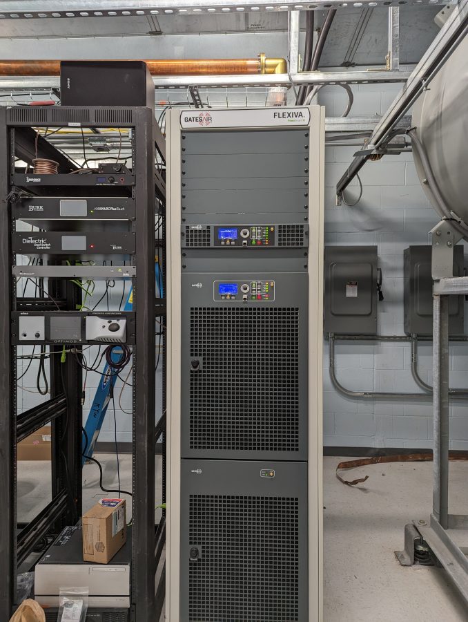
This thing is on the air! There are still some tidying-up things to finish, but it is up and running and sounds great! Here are some pictures of various stages of the installation work:

Making harmonic measurements

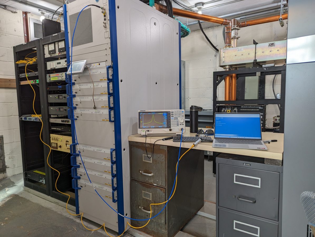
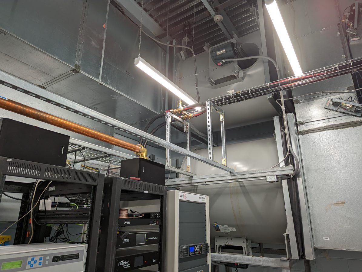
The filing cabinets hold manuals and spare parts. There is not a lot of room left in this building, so workspace is at a premium. The filing cabinet on the left needs some Windex and elbow grease.

Main disconnect and conduit to 400-volt transformer
Outdoor coolant run
3/0 cables, 240-volt input to Hammond HPS Sentinal K transformer

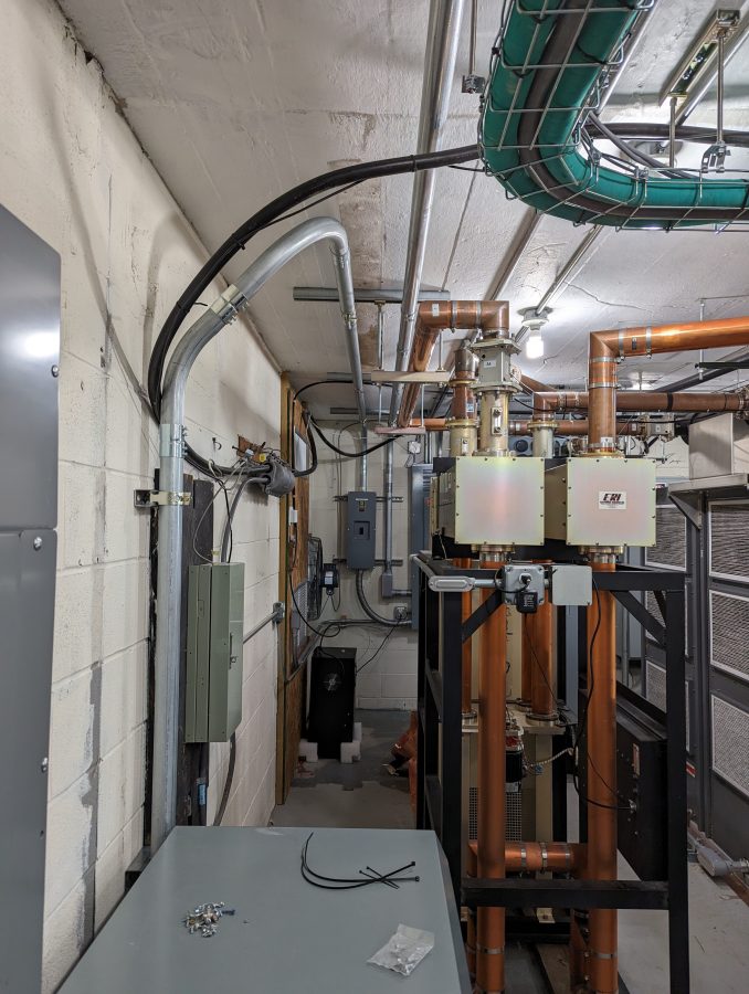
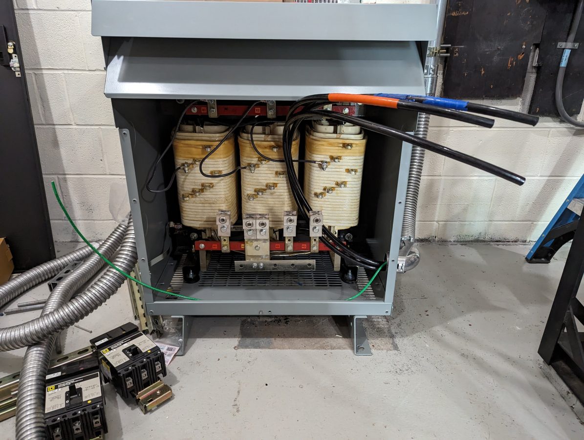
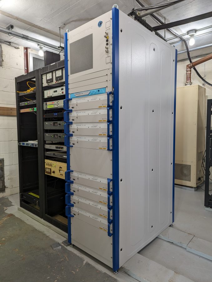
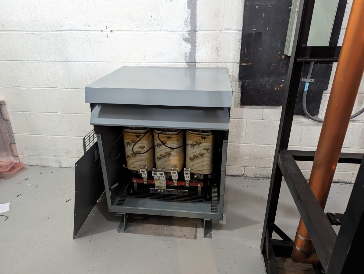
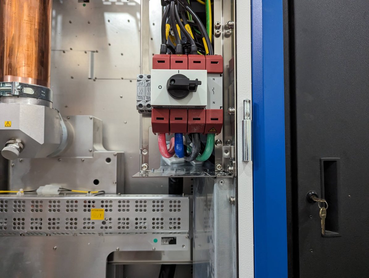
The transformer does not have a neutral reference to the power company. The neutral for the transmitter is derived from the Y output connection. The transformer is also designed to suppress harmonics from non-linear loads like switching power supplies.

Wiring in Square D I line panel
Square D I-line panel rated for 600 volts
#2 SOOW cable feeding upper and lower sections of transmitter
Wiring to disconnect switch on transmitter
Pump station during system fill
Heat exchanger

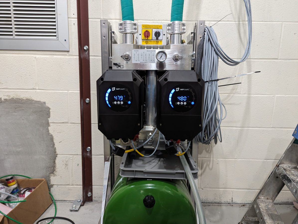
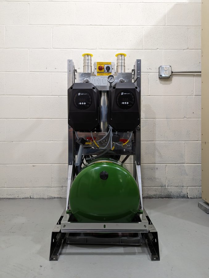
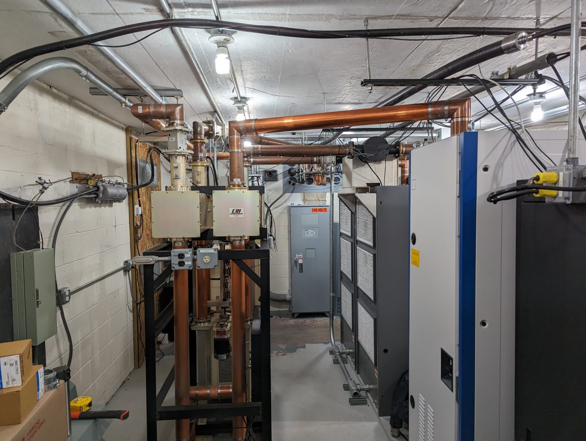
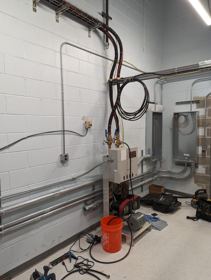
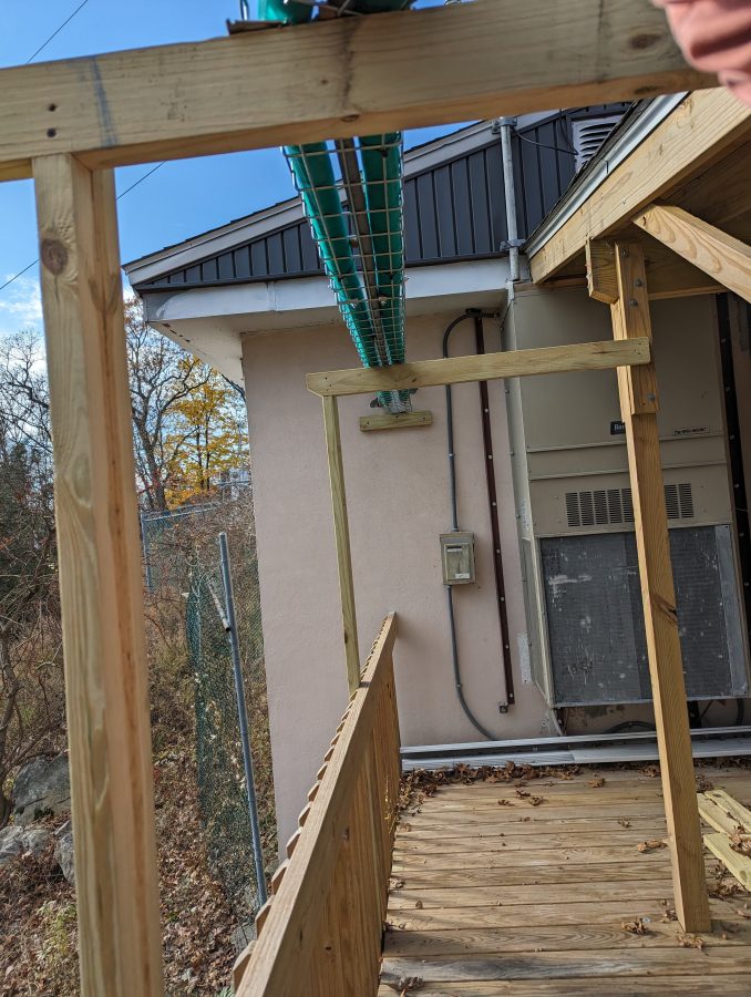
The wiring on the pump station and heat exchanger needs a little more work. The client wanted to get this on the air as soon as possible because they are in a book and were running at 50% power. Once things calm down a bit, I will put the backup transmitter on for an afternoon and properly dress the wires.

FM modulation analysis

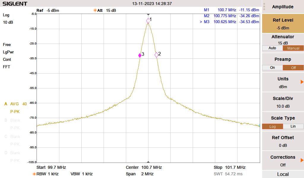
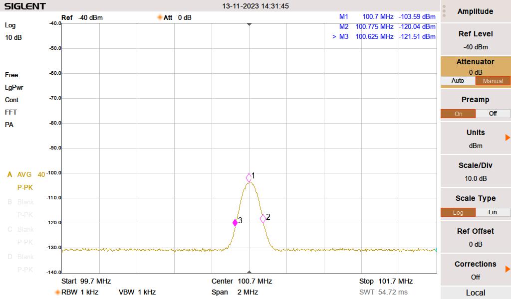
I found this FM modulation analysis function on my spectrum analyzer very useful. The station deviates slightly more than the allocated 75 KHz because of a subcarrier. Overall, it looks good. I measured the harmonics out to the 10th harmonic, most of them were in the noise floor. A few made a slight appearance, but well within FCC tolerances. It is important to document this, as this site has colocated cellular carriers and several E911 services.

FCC part 73.317 states:

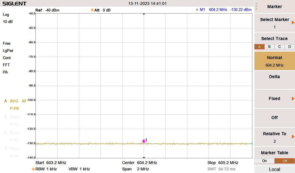
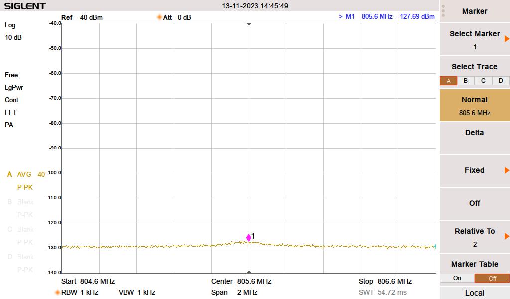
(d) Any emission appearing on a frequency removed from the carrier by more than 600 kHz must be attenuated at least 43 + 10 Log10 (Power, in watts) dB below the level of the unmodulated carrier, or 80 dB, whichever is the lesser attenuation.

47CFR 73.317
WHUD fundamental
WHUD fundamental with two Mini-Circuits NHP-200 high pass filters installed

The rest of the harmonics were measured down to -130 dB with the two NHP-200 high-pass filters in the circuit. The 3rd, 4th, 5th, 6th, and 8th harmonics were unmeasurable. The 8th, 9th, and 10th made slight appearances.

WHUD 6th Harmonic, noise floor
WHUD 8th harmonic makes a little appearance
Main antenna VSWR
Antenna VSWR according to the transmitter directional coupler

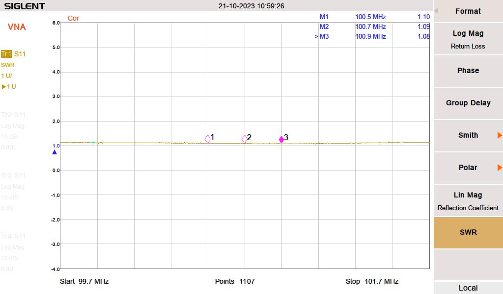
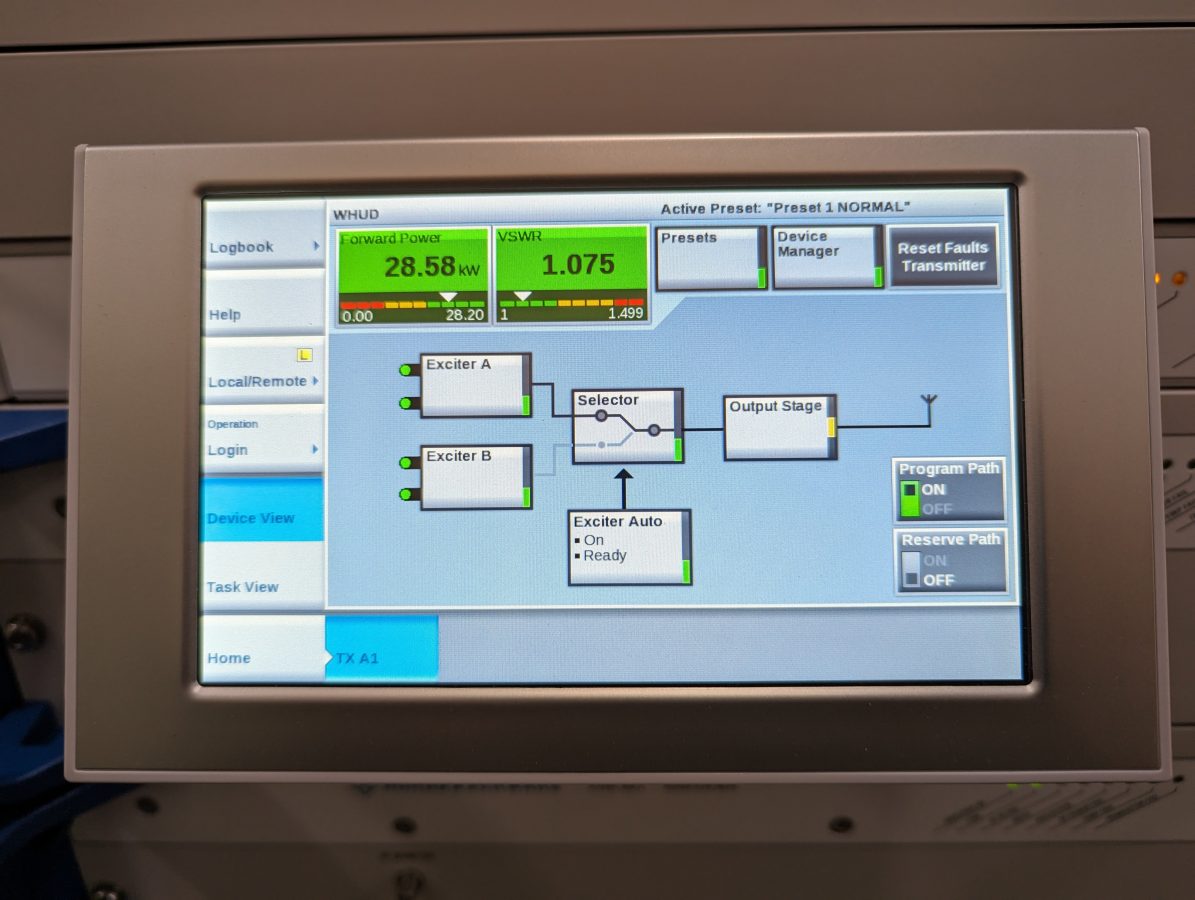
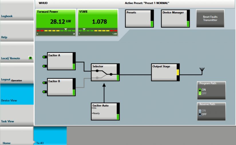
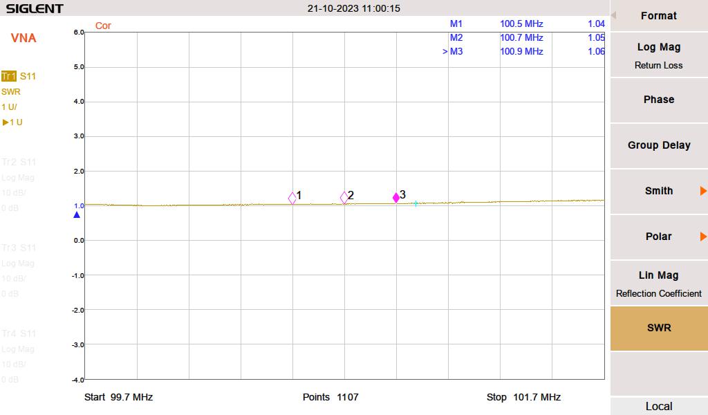
Pretty close, the VNA was inserted at a patch panel, which is the last thing before the transmission line leaves the building. The transmitter goes through an ERI switchless combiner, which probably gives it a slightly better load.

Backup antenna SWR

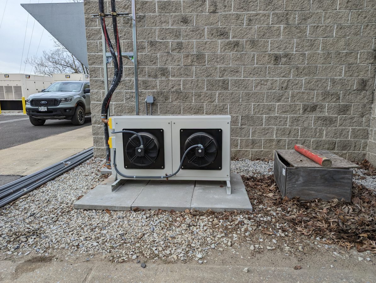
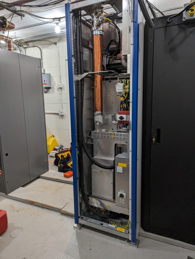
Aside from the finishing details, I need to keep an eye on this for a week or so and top off the Heat Transfer Fluid as needed. It takes a bit of time to get all of the air out of the coolant loop. Another thing; the operating pressure on this is 4 Bar, which is almost 60 PSI. That is higher than other liquid-cooled transmitter systems I have installed before.

The Rhode Schwarz THR9 transmitter

This is part I of II.

We are in the process of installing an R&S 40 KW liquid-cooled FM transmitter. My first comment; these are well-built units. A quick look at the machining of the parts indicates attention to detail is a key design feature.

As the price of electricity continues to rise, liquid-cooled transmitters for this power level make a lot of sense.

Rhode Schwarz THR9 VHF transmitter

This installation is for Pamal Broadcasting’s WHUD, Peekskill, New York. The site has undergone major upgrades in the last few years. The original 1958 World Tower Utility 80 was replaced a year ago with this Valmont 60X394. Two cell carriers, two translators, and several E911 services are now colocated on the tower.

Valmont 60X394 tower, WHUD Peekskill, NY

The transmitter building is also the original cinder block structure from 1958. When it signed on, the station had a Gates FM5B 5 KW transmitter, an RCA BFA-7, 7-bay horizontally polarized antenna with an ERP of 20 KW. In 1970, that antenna was changed out to a 6-bay circularly polarized ERI with a Harris FM20H transmitter, increasing the ERP to 50 KW. As of now, the station has a 4-bay ERI SHP-4-A-C main antenna and the TPO is 28 KW for the same 50 KW ERP. As the station’s power increased, the building became a little bit smaller than optimal. We needed to rearrange some equipment to gain space for the pump station and step-up transformer.

Pump Station
Heat Exchanger

Rhode Schwarz recommended installing a step-up transformer for the incoming AC mains. The power supplies run most efficiently with 400 volts AC.

Hammond HPS Sentinel K dry core transformer
The Rhode Schwarz RF connection to an ERI switchless combiner

We decided to reuse the ERI switchless combiner left over from the Nautel V-40 installation. There are two Nautel V-10 transmitters with a hybrid combiner that are to be used as a backup. We won’t be running this as a combined transmitter operation, it is a way to save money rather than install a separate 3-inch coax switch. I will build a simple control panel to move the combiner position either all the way up (THR9) or all the way down (V-10s).

2.5 inch core drilled holes for coolant supply and return

Working on the liquid cooling system. I used a core drill to make the supply and return lines to the outdoor heat exchanger. I made sure that I had the shop vac (with a HEPA filter) running while drilling so that all of the concrete dust was captured. That stuff can get everywhere and has a bad tendency to destroy motor bearings. Whatever plant made these blocks in 1958, they used some hard material. It took a while for my masonry drill to get through them.

One of the perks

Occasionally, I get to go for a nice walk in a snowstorm. No, I am not being sarcastic. It is the middle of March and winter has decided to make an appearance. One of the FM stations we take care of went off the air and the remote control was not able to get the transmitter to come back on, so a stroll through the woods was necessary. This station is located at Sam’s Point Preserve, in Craigsmore NY.

Self-supporting tower has ATT and a Low Power TV station

The site is owned by Vertical Bridge. There are a few tenants on the tower and fortunately, somebody left the gate open before it snowed. I was somewhat dreading trying to wrestle with it when I got to the site.

The problem itself seems to be due to a power hit; the main transmitter was off and the remote control, a wheezing Genter VRC-2000, was not able to control either the main or the backup. Those should be replaced at some point.

Neighboring tower

There are several other towers up here for various cell carriers, 911 dispatch, etc.

My SO decided to come along.

My phone said we walked 2.7 miles round trip, which sounds about right. The station is back on the air. When I can get up there with a vehicle in a few weeks, I will look into the remote control problem.

FLX20KFAX50K+HD

Greetings from the Roxborough tower farm, a place with roots. It is slightly northwest of Philadelphia, PA, and is home to many TV and FM stations. The public road that cuts through the tower farm is called Domino Lane because if one tower falls, they all fall. A comforting thought to those that live in the vicinity I am sure.

View from the residential neighborhood next to the site

The reason for the visit; this rather nice GatesAir FLX20 transmitter:

Newly installed FLX20+HD, WRNB Philadelphia, PA

I must admit, I am growing rather fond of these transmitters. This unit is being installed because the station had to move from its old site, just down the hill. The tower owner is taking down the tower and building due to the age of the tower. Thus, it was moved into the KYW-TV building. If Wikipedia is to be believed, KYW-TV is the oldest TV station in Philadelphia, signing on in 1932.

The site is still being built as we were installing this transmitter. These days, the electricians are having supply chain problems like everyone else. There were delays getting the large electrical panel board and other necessary things for the build-out.

Cooling system high point, sight glass, and air purge valve

Overall, the installation went well. This system is using flexible hoses for the coolant loop. We have installed two of these liquid-cooled transmitters with 1 1/2 copper pipe. These days, copper pipe is expensive, so most are opting for flexible hose installation.

Pump Station; system top off

Topping off the pump station after 50/50 fillup. After the initial system fillup, it takes a while for all of the dissolved air to come out of the Heat Transfer Fluid (HTF). The extra steps with a liquid-cooled system are worth it, especially if the station is running HD. With the HD carrier on, the transmitter efficiency is 54% AC to RF. With a TPO of around 15 KW, that is a whole lot of heat that needs to be dissipated during operation. It is much cheaper to pipe the heat outside to a heat exchanger than to use several tons of AC to remove it from the room.

Heat Exchanger

Overall, this was a fun project.