That is indeed a good question. There may be several explanations; a pirate, somebody’s Part 15 device, or atmospheric ducting. If the weather is good, tropospheric ducting can cause VHF (FM broadcast) and UHF (TV broadcast as well as Remote Pickup units and STLs) signals to travel far beyond their intended reception areas.
The Troposphere is the zone in the atmosphere closest to the Earth, ranging from 0 to 15 km. It is the area where most weather phenomena take place. For VHF and sometimes UHF, refraction can bend the signal back towards the surface of the Earth. Refraction at lower altitudes (called surface ducts) can cause radio signals to travel shorter distances than normal unless they are over water. Refraction at higher altitudes (elevated ducts) can cause those same signals to travel far beyond their normal range, sometimes hundreds or thousands of kilometers.
Three things affect the tropospheric refraction index (or N); water vapor, air pressure, and air density. At higher altitudes, the air is normally cooler, less dense, and dryer than air closer to ground level. However, high barometric pressure will often bring warm, dense, moist air to high altitudes. This can create a layer of warm air over a layer of cooler air known as a temperature inversion. This can create a “duct” in the upper troposphere similar to a waveguide. These signals can be very strong, sometimes overpowering a local FM signal due to the capture effect.
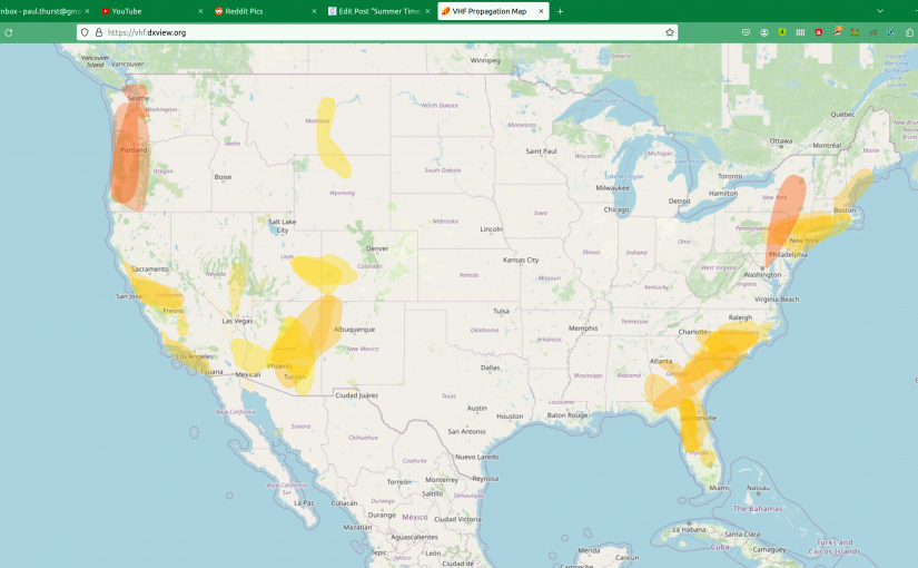
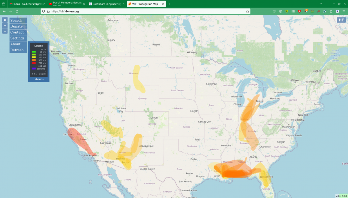
There is an online source that predicts atmospheric ducting, mostly used by Amateur Radio operators, but it can also be a useful troubleshooting tool: https://vhf.dxview.org/
That site produces a map like this:
This can happen any time of the year but is more common in summertime. Tropospheric ducting is not an effect of ionization from the sun. This phenomenon is known as Sporadic E, which will be covered below.
The good news is tropospheric ducts normally last a few minutes to a few hours. Sometimes they can last longer however changes in the width or length of the ducts will change the frequencies and distances that RF signals travel along that duct. In addition, if you are hearing a co-channel FM station from many hundred kilometers away, listeners of that station are now hearing your station the same way.
Another long-distance VHF propagation phenomenon is called Sporadic E layer propagation or simply Sporadic E. This happens when the Ionosphere is heavily affected by a solar storm or sunspot. Sunspots run in an 11-year cycle. We are approaching the solar maximum for Solar Cycle 25, predicted to happen in July 2025.
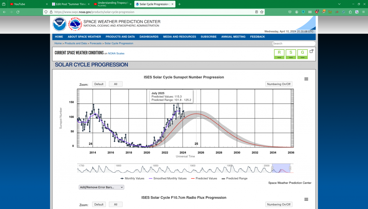
Sporadic E is much less predictable, more random, and short-lived. Solar storms can create highly ionized areas in the E layer of the Ionosphere, creating skywave conditions for VHF signals. These signals will skip in the same way that HF and MF signals do. Fortunately, these conditions usually last a few seconds or minutes at most. More on the solar cycle can be found here: https://www.swpc.noaa.gov/products/solar-cycle-progression
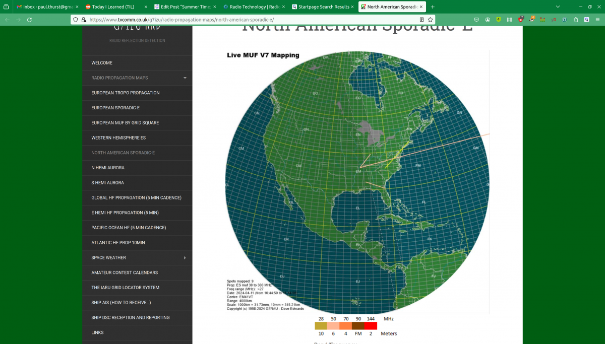
Once again, Amateur Radio operators are interested in this as a mode of communication. There is a Sporadic E map online at: https://www.tvcomm.co.uk/g7izu/radio-propagation-maps/north-american-sporadic-e/