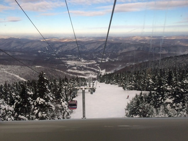
What better time to take the gondola to K-1? None, none at all. We do work for the two radio stations that are on the peak of Mount Killington, near Rutland, Vermont. In the summer, usually, we can drive up there in a four-wheel drive truck. In the winter, the gondola is the way to go. On this day, there was a 48-56 inch base, light north winds, and air temperature around 10° F (-12° C) .
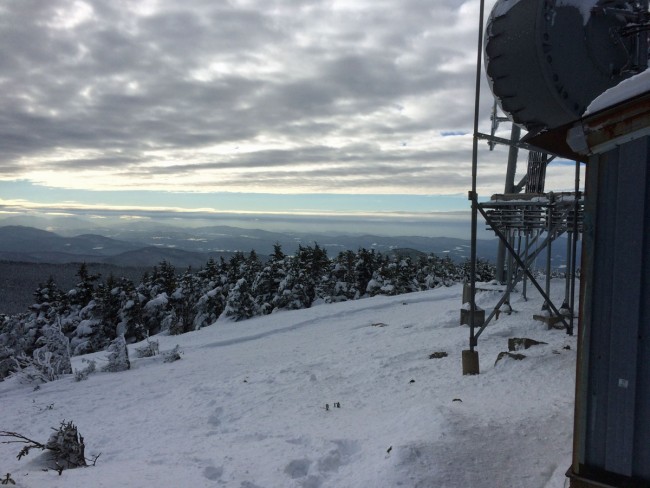
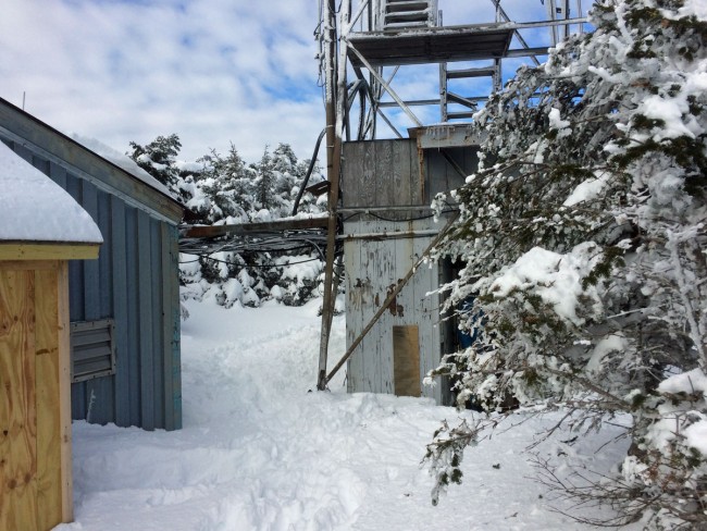
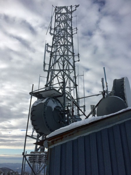
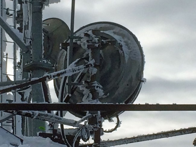
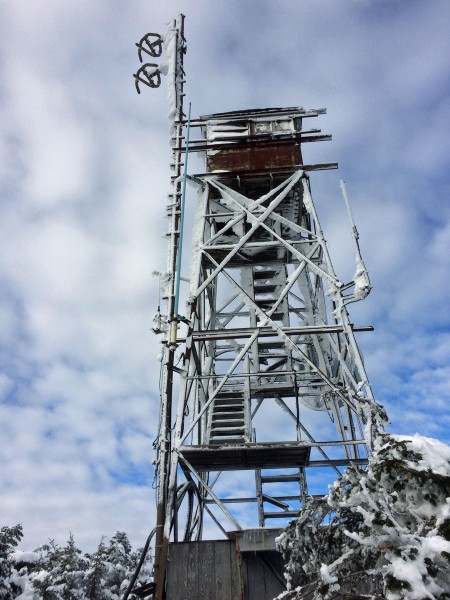
Ride up to Killington PeakView from Killington PeakTransmitter buildings on Killington PeakView from Killington PeakTower from Killington PeakKillington STL dishesERI antenna, WZRT/WJJR Killington VT
The reason for the trip today; is repair work on the Nautel VS2.5 transmitter. All three power supplies and the power supply summing board needed to be replaced.
In the progression from Circuit Switched Data to Packet Switched Data, I can think of many different applications for something like this:
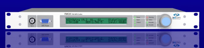
FMC01 MPX to IP CODEC
The FMC01 MPX to IP encoder can be used for multi-point distribution (multi-frequency or same-frequency network) of FM Composite audio, or as a backup solution over a LAN bridge, LAN extension, or public network. I can think of several advantages of using this for a backup when composite analog STLs are in use. There are many compelling reasons to extend the LAN to the transmitter site these days; Transmitter control and monitoring, security cameras, office phone system extensions, internet access, backup audio, etc. I would think, any type of critical infrastructure (e.g. STL) over a wireless IP LAN extension should be over a licensed system. In the United States, the 3.6 GHz WLAN (802.11y) requires coordination and licensing, however, the way the rules are set up, the licensing process is greatly simplified over FCC Part 74 or 101 applications.
Another similar CODEC is the Sigmacom Broadcast EtherMPX.
Sigmacom Broadcast EtherMPX CODEC
Features include: • Transparent Analog or Digital MPX (MPX over AES), or two discrete L/R channels (analog or AES). • Built-in MPX SFN support with PTP sync (up to 6.000km in the basic version). No GPS receivers! • Unicast or Multicast operation to feed an unlimited number of FM transmitters with MPX from one encoder. • Linear uncompressed PCM 24-bit audio. • Very low audio latency: 2,5mS in MPX mode. • Perfect match with Sigmacom DDS-30 Exciter with Digital MPX input. • Can be used with high-quality 802.11a/n Ethernet links. • DC coupled, balanced Analog inputs & outputs with -130dBc noise floor. • No modulation overshoots due to compression or AC capacitor coupling. • Decoder provides simultaneous Analog & Digital output for transmitter redundancy. • Aux RS232 serial transparent link, Studio to Transmitter. • Auto switchover to Analog input when Digital signal is lost. • Centralized remote control & management software
One last thought; separating the CODEC from the radio seems to be a good idea. It allows for greater flexibility and redundancy. Using an MPX-type STL allows sensitive air chain processing equipment to be installed at the studio instead of the transmitter site.
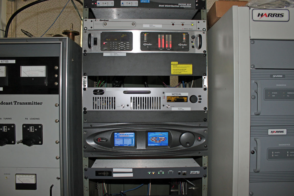
The news is out; this is for the new “WFAS-FM” which is actually W232AL retransmitting the WPLJ HD-2 channel. What do they call translators these days… Metro stations? Something like that. Anyway, quite a bit of work went into getting this off the ground before the start of Labor Day weekend and here it is!
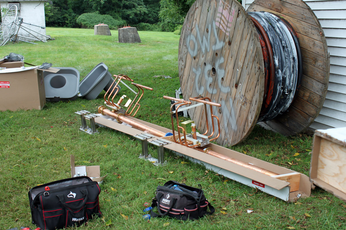
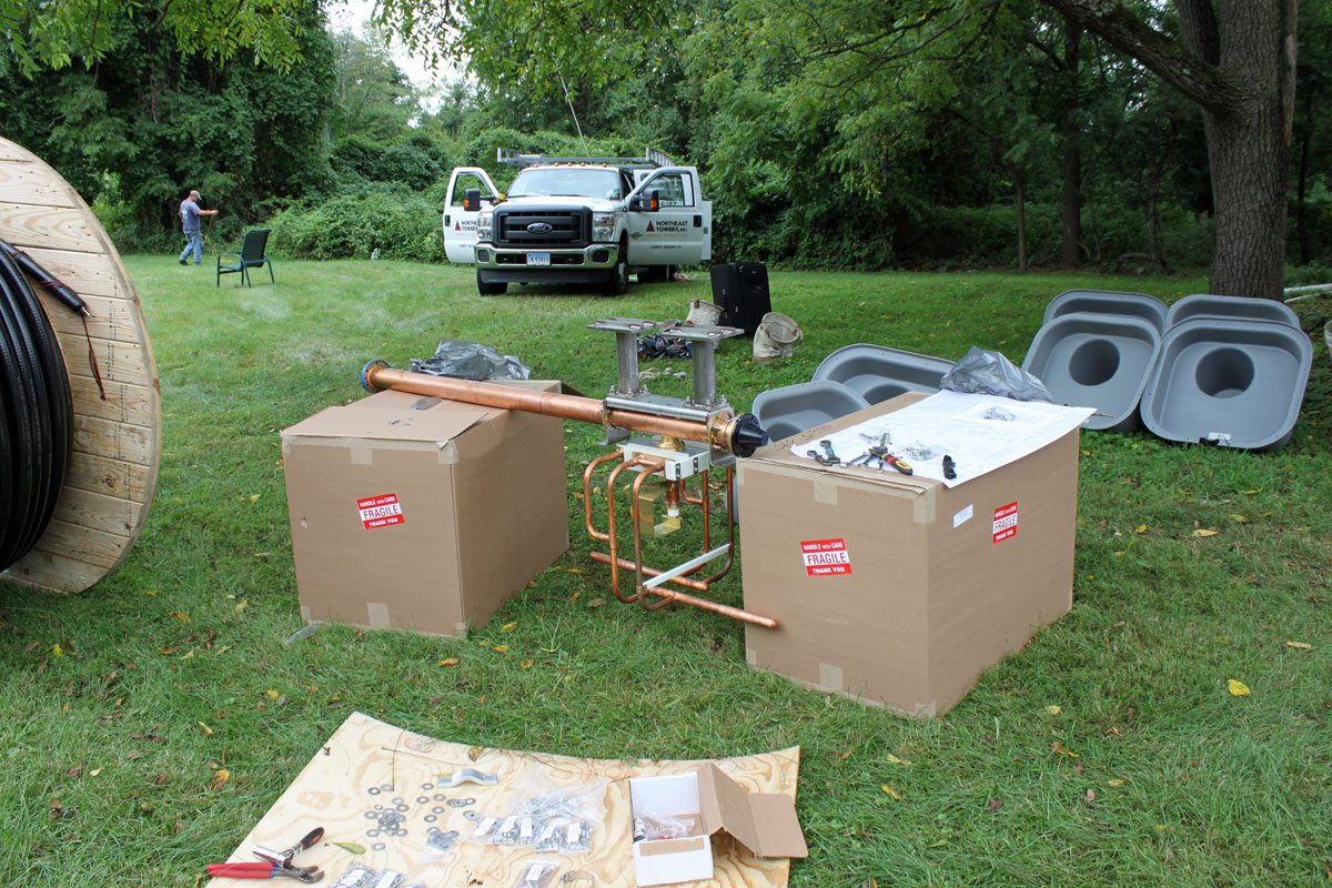
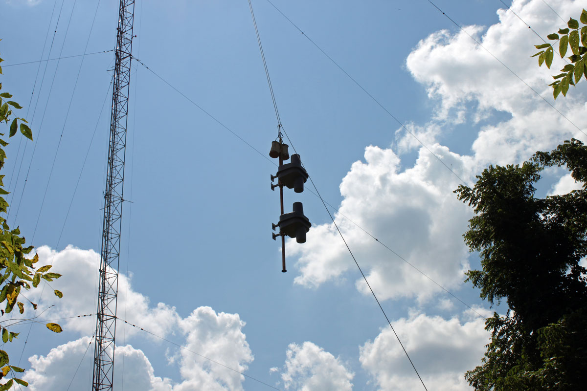
We are currently working on a project that involves installing a Shively 6810 FM antenna. Since few people get to see these things up close, I thought I would post a few pictures.
This particular antenna is a four-bay, half-wave spaced directional antenna. It is going to be side mounted on a 430-foot tower. To do this, we had to lower the AM skirt wires by about fifteen feet and retune the AM antenna.
This Shively antenna came in seventeen boxes with sixty-four pages of assembly instructions. There are many parts and they need to be assembled in the order specified, otherwise, things get in the way. We found that Shively provided many extra bolts, washers, O rings, etc because things get lost. Also, all of the parasitic locations and bay orientations were clearly marked. One thing that the tower crew said; always check the Allen screws and other hardware on the elements before installing the RADOMES.
Shively 6810 installing elements
Since this is a half-wave antenna, the radiating elements are 180 degrees out of phase, bay to bay.
Shively 6810 mounting brackets
Stainless steel tower leg mounting brackets.
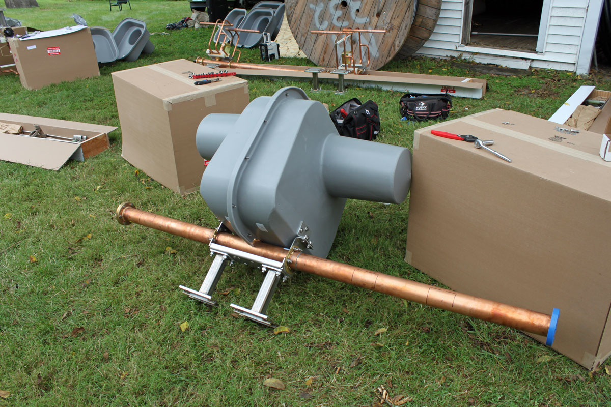
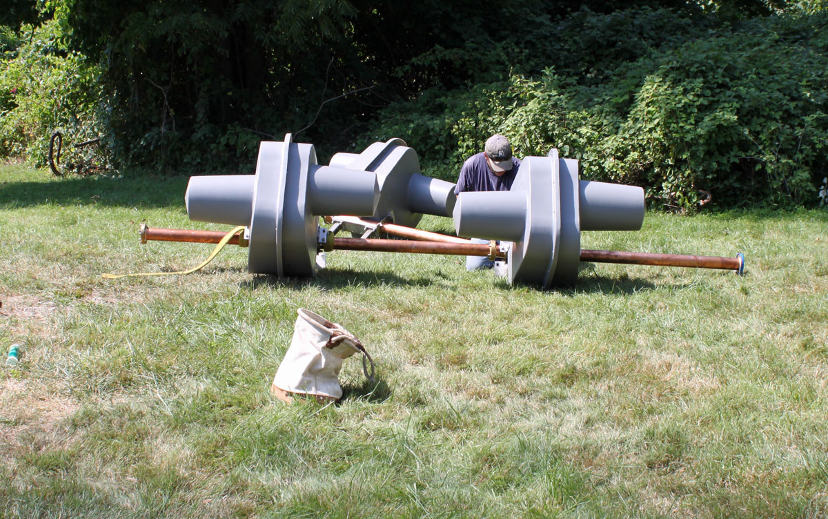
Assembled element with RADOME. This is the top bay with the gas pressure release valveShively 6810 top bays staged for hoist
We hoisted two bays at a time. The top bays are ready to go up.
Shively 6810 top two bays lift
The bottom two bays were hoisted next.
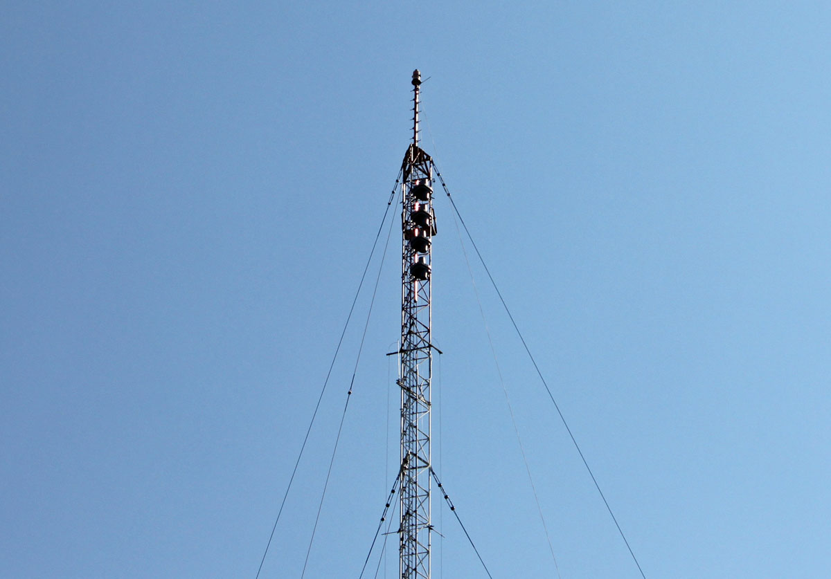
Shively 6810 four bays installed
This is the antenna installed, less the tuning section and parasitic elements. It is tilted off axis from the tower by design due to its highly directional nature.
The transmission line was installed and we swept the antenna. I will snap a few final pictures once the transmitter is installed, which will happen tomorrow.
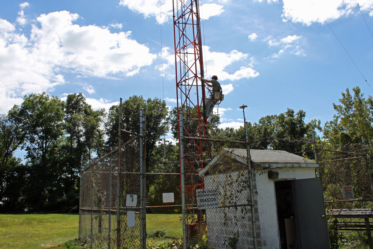
Updated Pictures: Here are a few pictures of the finalized installation:
W232AL antenna, new installation on WFAS AM tower
The fully installed antenna, tuning unit and transmission line. We did some program testing, made sure the audio sounded good, then the station was signed on. We also had to lower the AM station’s skirt a few feet and retune the ATU. Actually, the ATU needed to be reconfigured because the shut leg had been disconnected and there was a capacitor added to the circuit after the base current meter. All of that was fixed, along with a few other things…
W232AL transmitter, a BW Broadcast TX300 V2
The W232AL transmitter is a BW Broadcast TX300 V2. These little transmitter are packed with features like a web interface, on board audio processing, etc. They are pretty neat.
It’s Friday, time to go home!
The tower crew from Northeast Towers did a great job, as they always do.
I alluded to this in an earlier post: Open Delta three phase service. Some transmitter sites are fairly remote and three-phase power is not available. Occasionally, with lower-powered radio stations, this is acceptable because those transmitters can be configured to run on single-phase power. However, almost any transmitter above five kilowatts or so will require three-phase power. This is the case at the WQBJ transmitter site in Palatine Bridge, NY. The site is located in the middle of farmland and only has single-phase service. The nearest three-phase service is several miles away and the utility company wants several hundred thousand dollars to upgrade the line.
WQBJ transmitter site electrical service
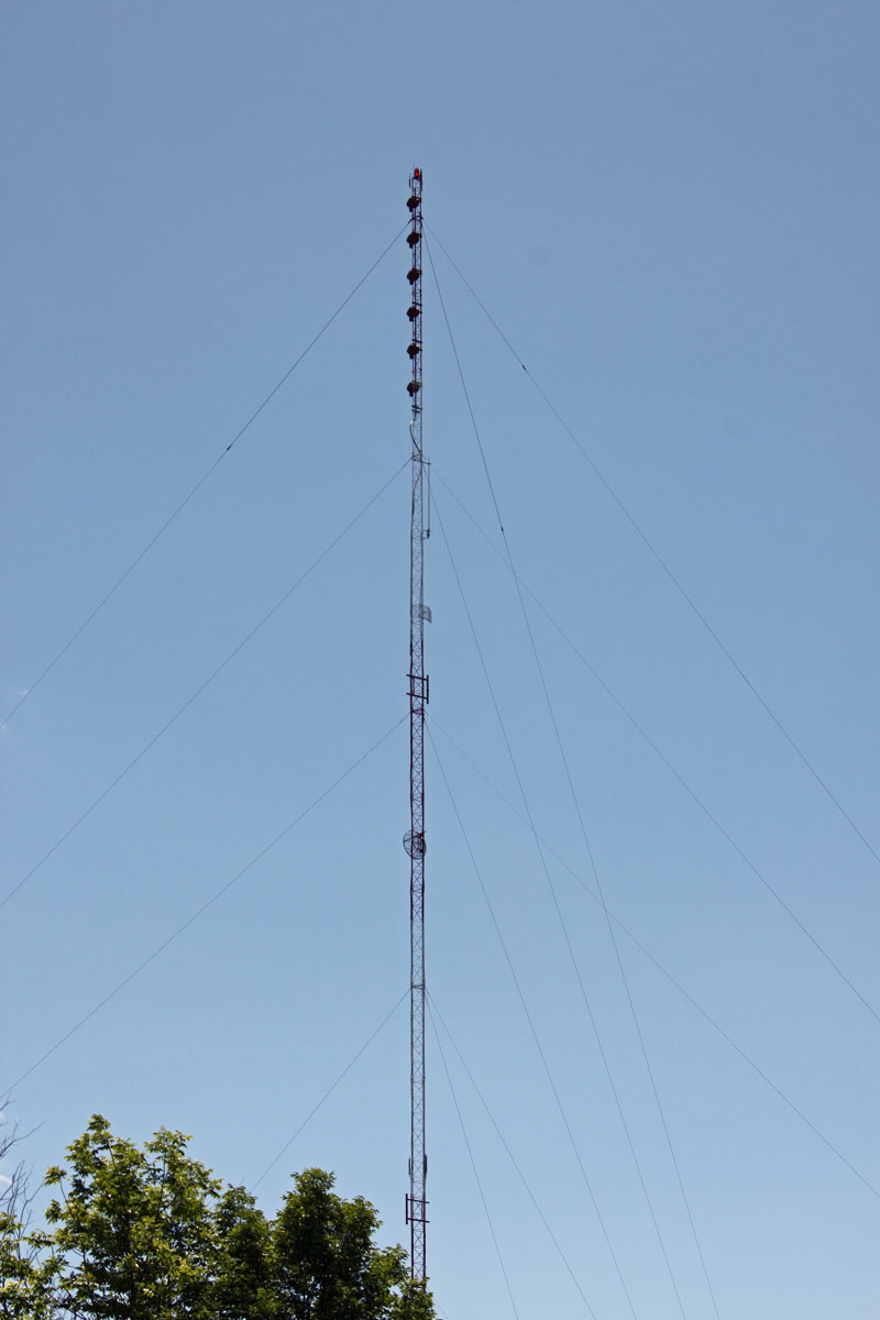
The station is a class B FM with a six-bay full wave-spaced antenna. Even so, the TPO is 17 KW, which makes some type of three-phase service a requirement.
WQBJ six-bay Shively 6810 antenna
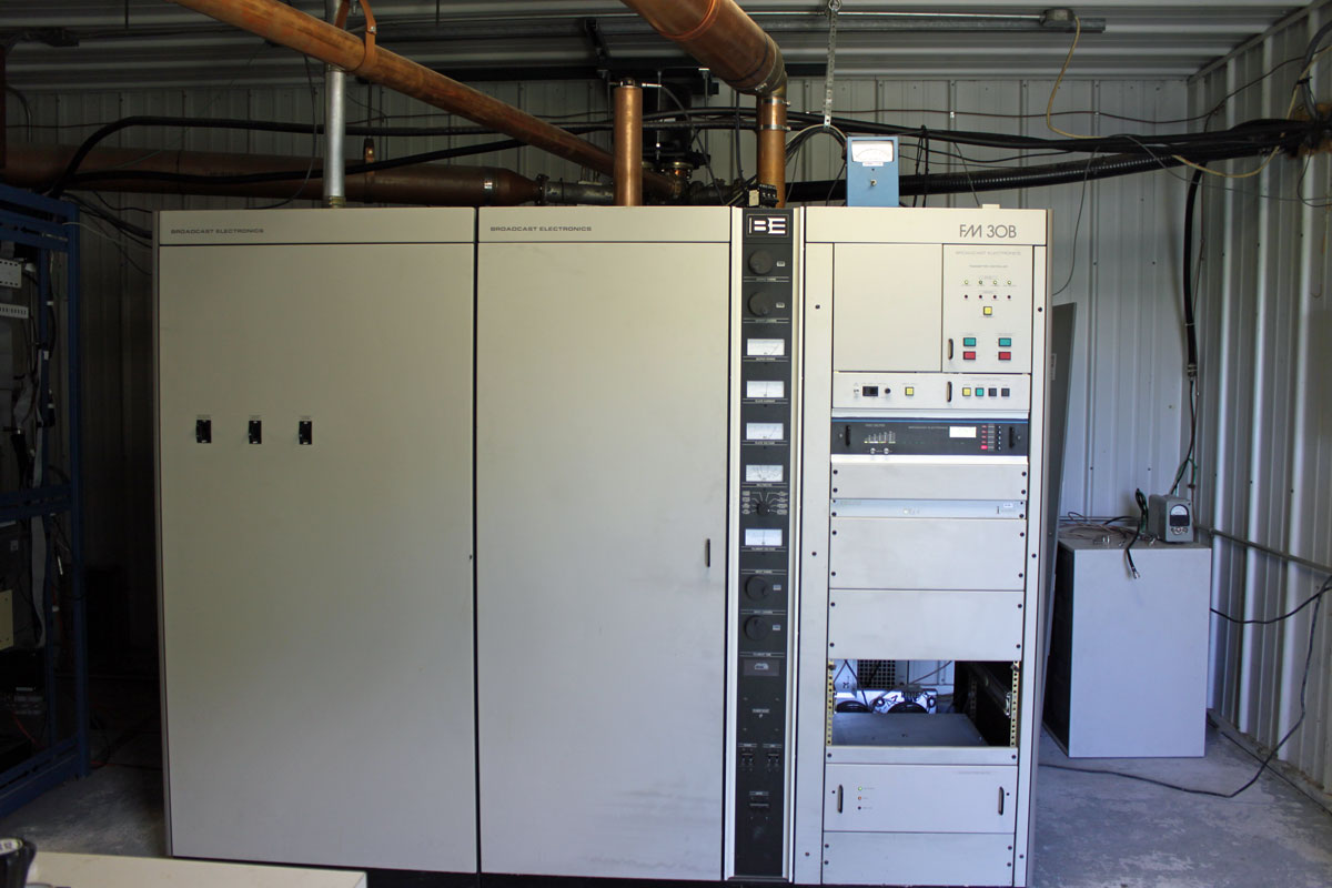
The main transmitter is a Broadcast Electronics FM30B, which is now 25 years old.
WQBJ main transmitter, Broadcast Electronics FM30B
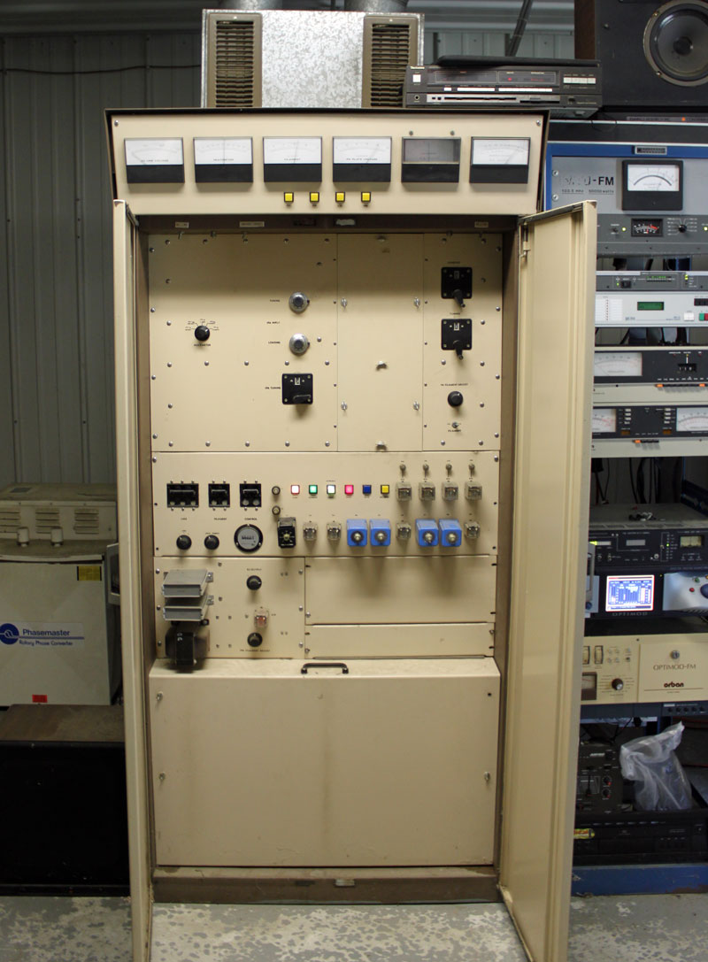
The backup transmitter is a CSI FM20T, which is almost forty years old.
WQBJ backup transmitter, CSI FM20T
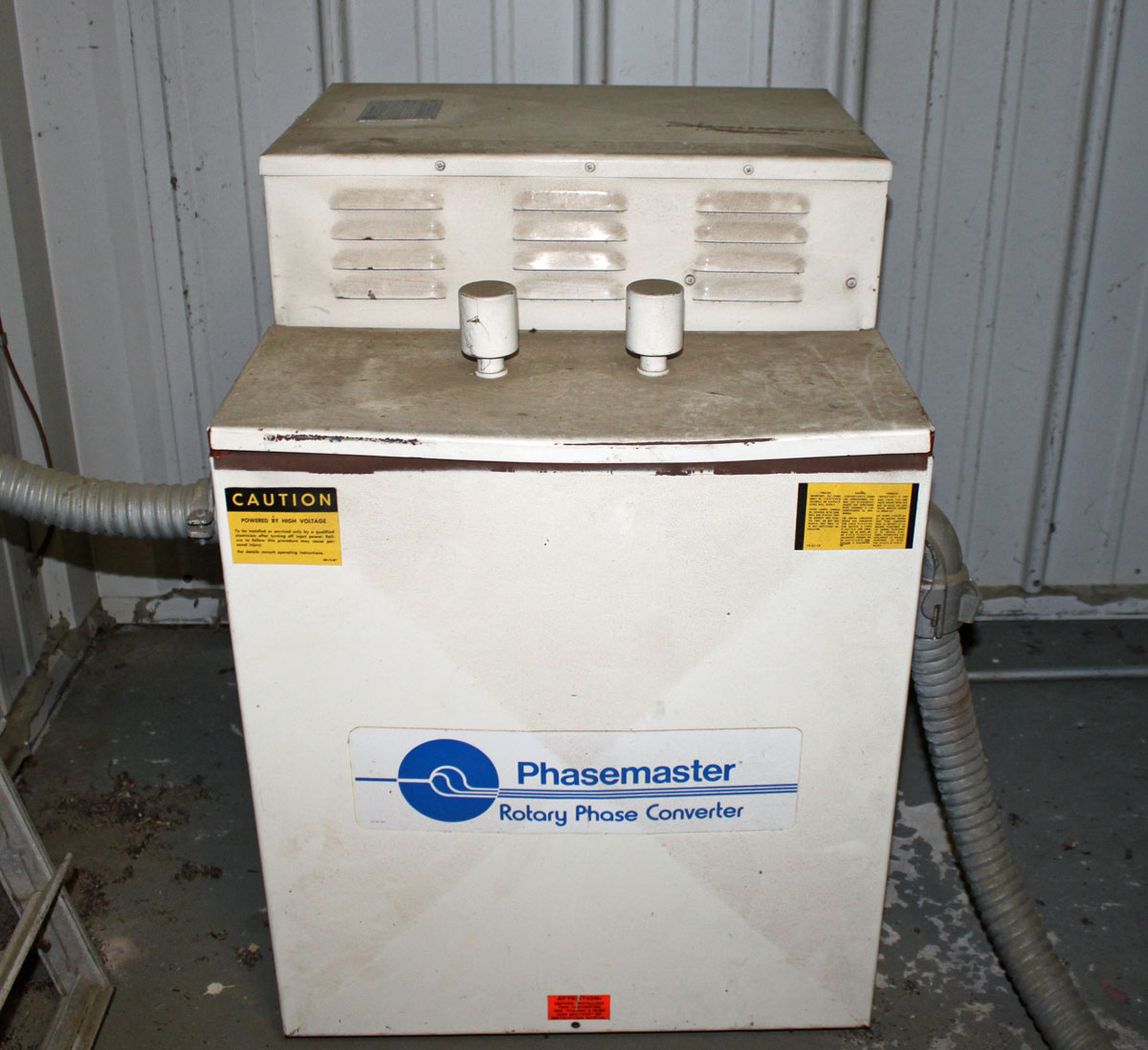
Rather than do an open delta service, which is not desirable for several reasons, both transmitters have their own rotary phase makers. From a reliability and redundancy standpoint, this is the right way to equip this site. The rotary phase makers are essentially a motor generator combination which takes the split phase power and generates a third phase.
WQBJ Phasemaster type T, backup three-phase converterPhasemaster parallel connection diagram
The phasemaster is is a 40 KVA unit and is connected to the backup CSI transmitter
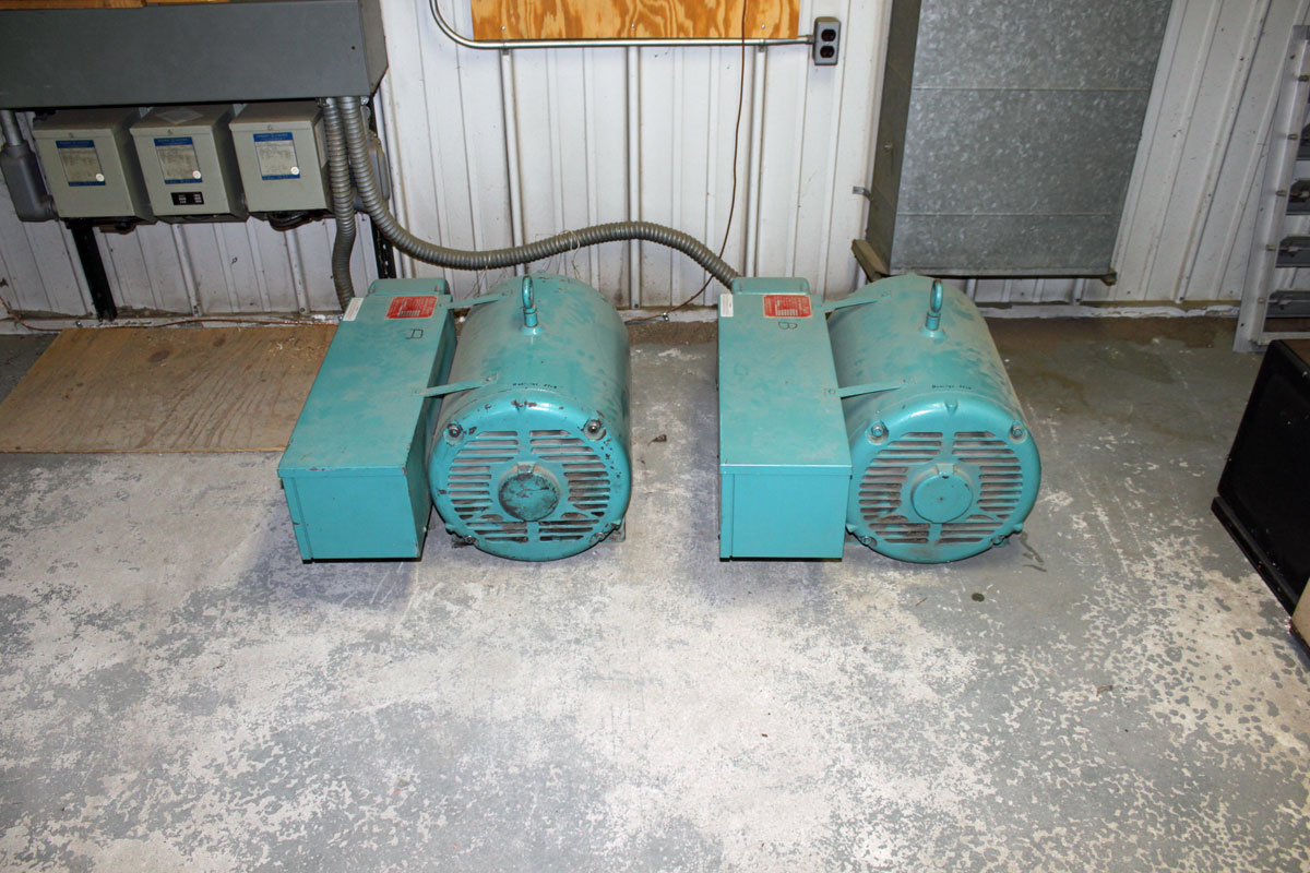
WQBJ ARCO Roto Phase, main three-phase rotary converter
The Roto Phase unit for the main transmitter is actually two 40 KVA units connected in parallel through dry core isolation transformers. Incidentally, the Roto Phase units need to have their bearings changed every ten years or so. This requires the units be disconnected, placed up on their end. To get the old bearing out, the housing has to be cooled with liquid CO2. Both units are due for new bearings soon, which should be a pleasant job indeed.