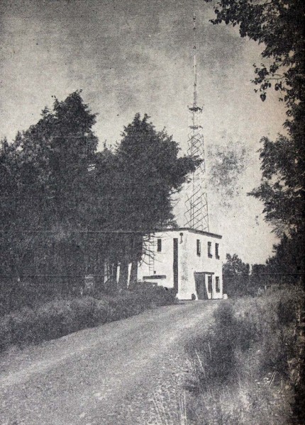
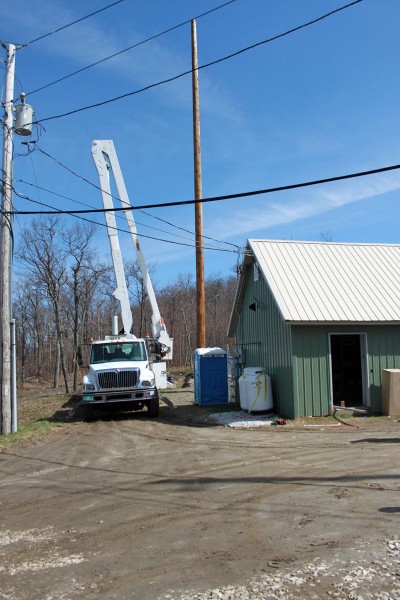
Several months ago, I drove up to an FM transmitter site, looked up at the utility pole, and saw this:

Three-phase open delta is a bad hombre. Most, if not all, transmitter manufacturers will void the warranty of any transmitter connected to a service like this. What is perplexing is it appears that all three phases are available on the primary side, why would this be necessary? Perhaps it was not always so at this location. Regardless, this was the source of power for 20 KW FM transmitters since 1958 until we moved it to a new building last month.
According to a GE publication on transformers, open delta 3 phase power is undesirable because:
Although this connection delivers three-phase currents which are approximately symmetrical to a three-phase symetrical load, the currents flowing in the high voltage circuit are not equal nor are they 120 degrees apart. The maximum safe output of the bank operating in this manner is 58% of a 3 pot Wye/Delta bank. The system is grossly unbalanced, both electrostatically and electromagnetically.
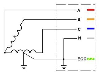
Schematically, it looks like this:
Regular 3 phase delta looks like this:
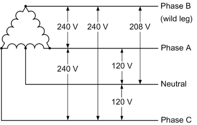
Most utility companies will not hook up 3 phase delta on the customer side anymore because the “high” or “wild” leg, which as shown in the diagram runs a good deal higher than 120 volts to neutral. Hook up a high leg to a single phase 120 volt piece of equipment and wait for the power supply to blow up. Also true with 277-volt lighting circuits, as my assistant once found out with the Coke Machine in the break room. The new 3 phase service will almost invariably be 208 wye unless there is some very compelling reason, which is fine.
There are many ways to get around three phase open delta, perhaps the best is a rotary phase converter. This piece of equipment will take a 240-volt split phase and add a third leg. These legs will not be 120 degrees apart, as they would be in a true three-phase, however, they will be close enough that 3 phase motors and transformers will be happy.
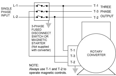
This leads to an unbalanced voltage/current condition which needs to be accounted for in the design of the unit. The second way to do this is to power a three-phase generator with a split-phase motor. This will completely isolate the 3 phase equipment from the utility service and provide for true three phase power.
The downside to any motor/generator or rotary converter is moving parts and conversion inefficiencies. At any transmitter site that uses this type of equipment, either a backup power converter or a lower power split phase backup transmitter should be installed. With all mechanical things, eventually, this will need to be repaired and it would suck to be off the air while that is happening.
Regardless of any of that, this particular service is about to be disconnected permanently. Good riddance.



dear admin,
please brief me about why we connect the common point to ground in open delta connection of transformer.
thanks
It is marked in the diagram.
ed note: I am very leery of giving out this type of advice on a blog. Basically, of OP does not understand a basic electrical diagram, then perhaps he or she should find somebody that does, especially when dealing with 3 phase open delta. Multi-phase industrial power systems are not something to be trifled with.
From the OP’s question I surmise he is not familiar with our earthing (grounding) requirements.
First and foremost, I am neither an engineer nor an electrician! Before retiring I was what is often referred to as a “low voltage guy” (alarm systems, sound, access control, etc, under 48 volts).
I was never able to find an electrician with enough stamina to get three-phase power systems through my thick skull so after retiring, I started investigating three-phase on my own. I understood different phases but not the differences between “delta” and “star” (wye) or why both are used. After much self-study, I now consider myself to know enough to be dangerous. 🙂 (For those familiar a certain TV commercial, “I did stay in a Holiday Inn last night.”)
The center-tap on the secondary of winding AC is the neutral for the 120 volts (split phase). Our electrical codes require the common point (neutral) to earth (ground) connection. If there were no center-tap, no N (neutral) would exist.
Our earthing (grounding) system is TN-C-S; Protective Earth (ground) and N (neutral) are common up to a point and are separate from that point on.
I hope this helps. TO ALL READERS: If I’m wrong anywhere point it out; I’m thick skinned.
I’d suggest Asjad get a copy of the GE power distribution transformer handbook:
http://www.etgiftstore.com/ge-distribution-transformer-manual-2485t-detail.htm
it’s inexpensive at $27 and pretty much the bible for transformer setup.
A second reference which covers power distribution systems from the ground up is available here at no cost:
(removed dead link)
@ChuckGennaro: Your 2nd link appears to be non-functioning. Can you please verify?
There are many ways to get around three phase open delta, perhaps the best is a rotary phase converter. This piece of equipment will take a 240 volt split phase and add a third leg. These legs will not be 120 degrees apart, as they would be in a true three phase, however, they will be close enough that 3 phase motors and transformers will be happy.
This isn’t correct. You have to remember that the phase converter isn’t generating one more phase it is creating two more phases. The phases are not the wires but the potential between those wires. The single phase power isn’t two phases only one using two hot wires to power one phase of the 3 phase motor where the wires are connected to the windings 120 degrees apart on the 3 phase motor. This is why if you disconnect any one wire you only have single phase not two phase power.