Guess what caught fire this time? It’s this thing, which has become the newest piece in my burned-up shit collection:

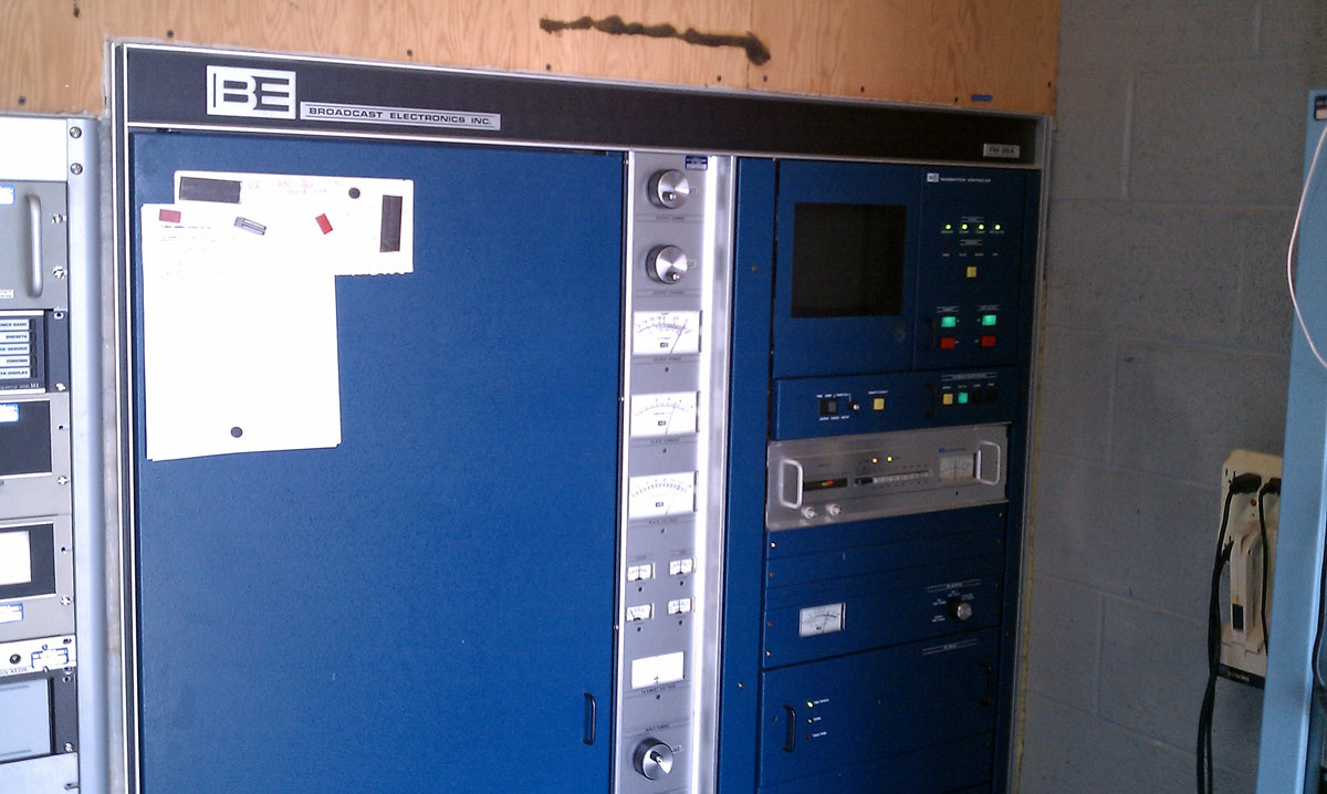
If you give up and are totally flummoxed, this is the IPA power supply regulator for a BE FM35A transmitter. Here it is in better days when it was actually working. The IPAs are in pull-out drawers on the right side of the transmitter cabinet, below the FX-30 exciter.
Said transmitter is aging not so gracefully, as it turns 26 this year. There does seem to be a finite life to transmitting equipment, something that should be kept in mind when planning out next year’s capital expense budgets. Regardless of all that, this event naturally occurred the day after Thanksgiving.
The good news, and there is always good news, we have many spare IPA regulators and PA modules in the shop ready to go. Upon investigation, there were numerous other problems with this transmitter, which have been or will be addressed.


