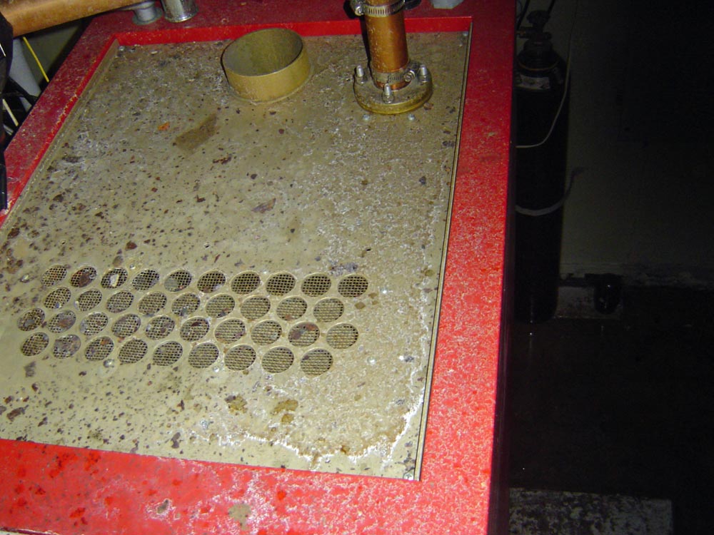
This incident happened a few years ago. I thought I had lost the pictures of the disaster, but I found them this morning on my thumb drive. Hooray! This occurred one morning just before Christmas after the area received a snow/ice/rain storm. The gutters on the old ATT long lines building were clogged with ice and the water on the roof built up. Unfortunately, the transmitter was installed directly below a disused exhaust stack for the former backup generators.
I received the off-air call from the morning show while I was driving to the office. I diverted and went to the transmitter site and found water pouring into the top of the main transmitter.
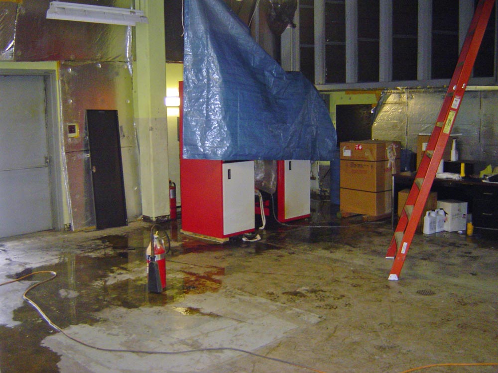
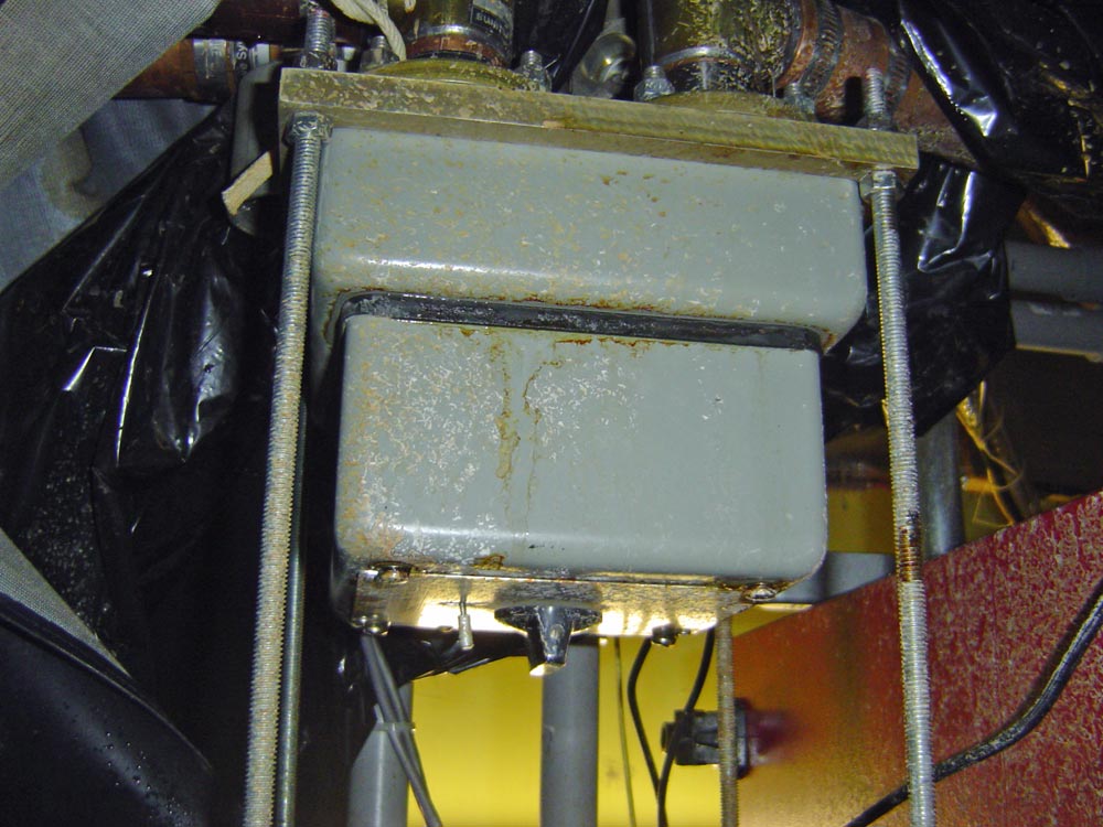
Thus, water ran down directly into the top of the QEI FMQ-3500 transmitter (transmitter was upgraded to 6 KW). Unfortunately, high voltage and dirty stack water do not mix. The combination of sooty, iron-laden water, and the B+ damaged much of the transmitter circuits beyond repair. The main transmitter is on the right, the backup transmitter is on the left.
I inspected the backup transmitter, also a QEI FMQ-3500, and it seemed to me that no water made it into the unit. I rigged the tarp to ensure that none did, which was a very pleasing bit of work, what with the cold, smelly, dirty diesel water dripping on my head and running down my neck and back.
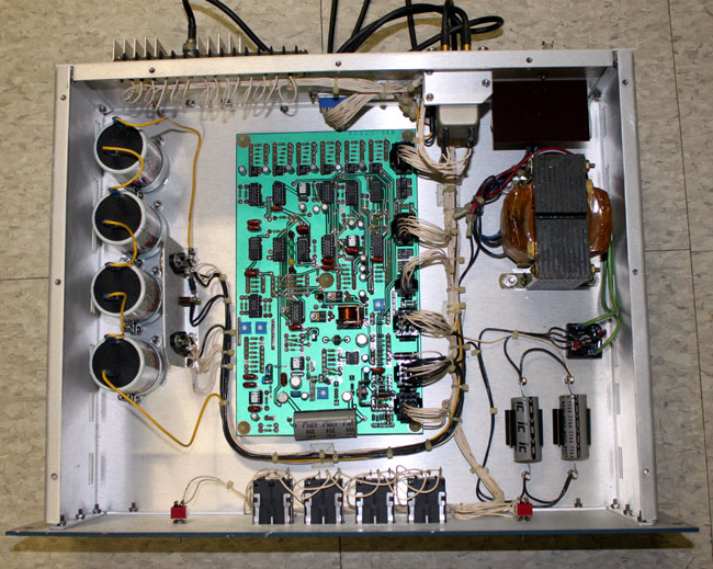
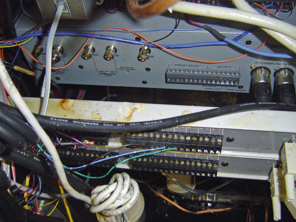
The 1 5/8 coax switch was also damaged:
As was the remote control in the equipment rack:
Fortunately, the backup transmitter ran, although I pressed the plate-on button with a dry wooden stick while standing on a dry, non-conducting ladder. Even so, I still felt a little trepidation holding that stick.
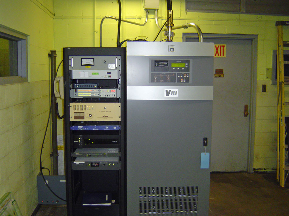
It took almost a year, but finally, the insurance company for the building owner came through, and a new Nautel V-7.5 transmitter was installed. I believe this is the last V transmitter Nautel made. We moved the transmitter location across the room, not under the old generator stacks. We also removed the generator stacks and patched up the roof with hydraulic cement and roofing tar. By the way, that yellow color should look familiar to anyone who ever worked inside a Bell Telephone System building.