WSPK antenna replacement, part I

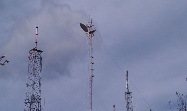
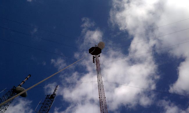
WSPK is located on North Mt. Beacon, which is the highest point for miles around. It has a fantastic signal. The site is a little difficult to get to, however, especially in the winter.  In previous years, the road has been impassable four months out of the year.  Some engineers have hired a helicopter to get up there when the snow is deep.  For that reason, it is important to keep the equipment in good shape.

WSPK Shively 6810 antenna with damaged top radome

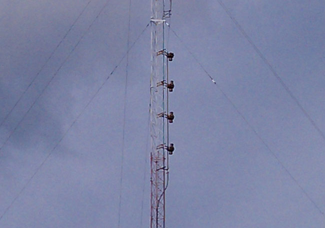
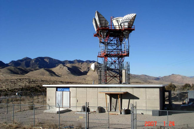
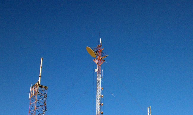
After last February’s snow/rain/ice storm, it was noted that the top antenna radome was missing its top.  A tower climber was sent up to look at it and it was also discovered that the top bay was bent down and the element was almost cracked in half.  A result of falling ice, likely from the big periscope microwave reflector (passive reflector) mounted above it.

WSPK tower
WSPK tower

The periscope reflectors went out of service in 2007, but the tower owner did not want to pay to take them down, thus a problem was not being solved.   It was decided to replace the 25-year-old Shively 6810 antenna with a new one, during which work, the radio station would pay to remove the reflectors from the tower.  In exchange for that work, the radio station would then be able to repair and remount the old Shively antenna below the new one, thus having a backup antenna.  Problem solved, except for, you know:  The actual work.

The tower and the periscope microwave system were installed in 1966, operated on 12 GHz, and were used by the Archdiocese of New York to relay their educational television programming from their Yonkers headquarters to the various schools in the Hudson Valley.  Sometime around 1975 or so, the FCC mandated that periscope microwave systems could no longer be used due to all the side lobes and interference issues they caused.  They were to be taken out of service as soon as possible.  The Catholic Church, being a multi millennial organization figured “as soon as possible” meant within the next fifty years or so.  Anyway, somebody else needed that frequency, therefore in 2007, they bought the Archdiocese a new digital microwave system.

The problem with the reflectors; they are big.  They are also heavy, and present a huge wind area.  They are also 300 feet up in the air.

WSPK tower periscope reflectors seen from ground level
WSPK tower periscope reflectors seen from ground level  

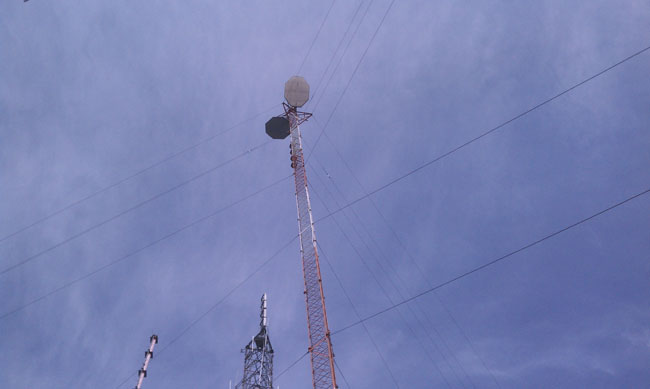
Finding a day with lite winds on top of Mount Beacon can be a problem.  Luckily, the weather was with us.  Still, it took a while to get this work moving along.  The other consideration is RFR and tower climber’s safety.  There are two digital TV stations, WSPK, several cell carriers, something called “Media Flow,” and a bunch of two-way radio repeaters.  The main concern was WSPK, the DTV, and Media Flow since the top of this tower is right in the aperture of those antennas.  All either went way down in power or off the air while this work was ongoing.

Rigging a gin pole and getting it to the top of the tower was a chore.  The gin pole needed to be threaded through those torque arms like a needle.

Gin Pole
Gin pole

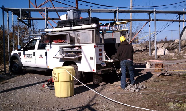
The tower riggers truck had two winches, one a basic 120-volt capstan, the other a hydraulic winch in the bed of the truck with 1/2 inch steel cable.

Tower rigger's truck
Tower rigger’s truck

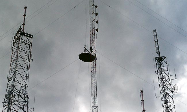
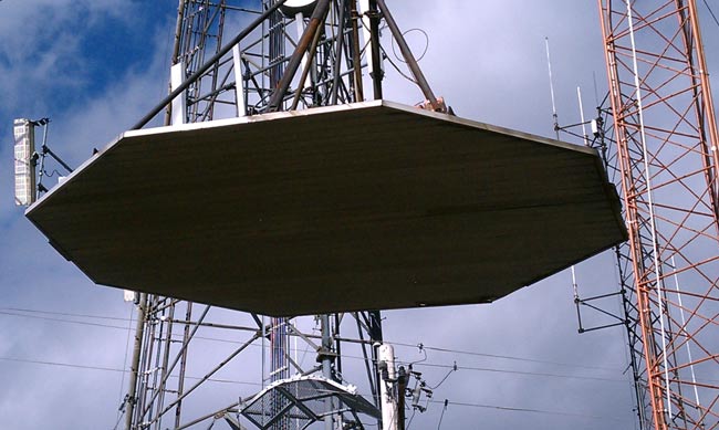
The bolts holding the reflectors in place had to be cut with a saw, you can see the tower climber working on the left-hand reflector, which gives you an idea of size.  If this reflector were to fall off the tower, chances are good that major damage and or injuries would result on the ground.  Proceed with extreme caution.

Cutting bracket mounting bolt on periscope reflector

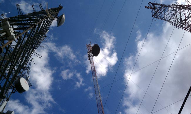
Carefully lowering reflector past Shively 6810 FM antenna and Scala PR-950U microwave antenna.  During this phase, the tower climbers had to push the reflector out away from those obstacles with their legs.  You can see the gin pole at the top of the tower.

lowering periscope reflector
Lowering Periscope reflector

Another view:

Lowering reflector
Lowering reflector

Another view:

Lowering reflector
Lowering reflector

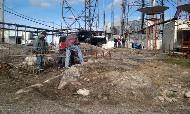
Almost down to the ground.  This measured 15 by 10 feet and ended up weighing 830 pounds.

Reflector almost to the ground

One down, one to go.  I can’t believe those gigantic things were at the top of this tower, on the top of this mountain for 43 years and the tower is still standing.  This is going to change the appearance of the mountain top from down below.  For years, it looked like a pair of mickey mouse ears, now it will only look like a tower.  I wonder what the environmentalists will think.

I will make a second post with the antenna pictures as this one is getting a little long.

FM antenna mounted on the side of a smokestack

If a person were to drive south down I-95 through Bridgeport, CT and look off to the left, they would see a 500-foot smokestack for a coal-fired power plant.  Side mounted on that smokestack is a 6-bay Shively FM antenna.  The antenna is more visible when driving south.  That would be the antenna for WEBE 107.9 Mhz.  This is right downtown, therefore, I would imagine this station has no problems with reception.

Bridgeport Power Plant smokestack, viewed from the west

WEBE is a class B FM with a full 50 KW ERP.  Most FM’s around here take advantage of a nearby mountain to gain some altitude and thus reduce the TPO a bit.  There are several class B stations that run less than 5 KW into a relatively small antenna, but they are way up in the 900 to 1000-foot HAAT range.  In this case,  the power plant is located right on the Pequonnock River Bay, so the AMSL at the base of the smokestack is only 10 feet.  This means lots of watts out and a fairly large antenna.

They are using Broadcast Electronics FM35A for the main and backup transmitters.  They were installed in late 1986 and are a little long in the tooth.

Broadcast Electronics FM35A transmitter

They run near a 12 KV plate supply, about 3.8 amps making 34 KW TPO.  That goes into a six bay Shively 6 bay 6813 antenna centered at 475 feet, which makes the HAAT 117 meters.

One of the problems encountered at the site is the smokestack emissions.  It seems that a fair amount of mercury comes out to the top of that thing.  In the past, this has caused major problems with the antenna shorting itself out and burning up transmission line.  Because of this, the entire antenna system, radomes, and transmission line is supplied with Nitrogen from this liquid nitrogen tank:

Liquid Nitrogen Tank

The antenna then intentionally bleeds N2 into the radomes continuously, overpressurizing them,  to keep the smokestack emissions out.  This type of tank is needed because a conventional N2 tank would last about a day, whereas the liquid tank lasts about 20 days.

The BE FM35A decided to blow a 200 Amp fuse on Friday afternoon:

Blown 200 Amp fuse

I had a BE FM30A that would randomly trip the 200 amp main breaker every once in a while.  I could never find anything wrong with the transmitter, it would just come back on and run normally again after the breaker was reset.  I even replaced the breaker thinking breaker fatigue.  Still happened.  In the end, we replaced that transmitter.  In this case, I don’t see that happening anytime soon.

BE FM35A heavy iron:

Broadcast Electronics FM35A plate transformer

I would not want to replace this thing, it must easily weight 1,000 pounds.

And rectifier stacks:

Broadcast Electronics FM35A rectifier stacks

12,000 volts DC.  That will light up any dirt, dust, piece of fuzz, etc. in the transmitter.

It is one of the more unique FM transmitter sites I’ve ever been to.  Every time I see it, I am reminded of that song, Smokestack Lightning. My favorite version of that song is the live recording by the Yardbirds

Somewhere in Utah, a phone company is missing it’s microwave site…

I followed this link to this site called “SurvivalRealty.com” and saw this article about what looks to be a former ATT microwave relay site in Utah turned into a residence.  The site is much smaller than the former ATT site in Kingston that I profiled in this post.   Still, that is a Western Electric tower and those are KS-15676 antennas.

Former ATT microwave site turned into a residence

If I were that guy, I’d take those antennas down a scrap them.  Looks like the waveguides are already gone.  I might have tried to put some windows in while I was renovating it.  It would drive me crazy to live in a house without any windows.  I guess if one were waiting for the big one, windows might not be a desired feature of a survival bunker.

I wouldn’t really call it a “communications bunker” though.  I’ve been in communications bunkers, they are mostly underground and are much more robust than that building.  Still, it is built better than an ordinary commercial building or a regular house.   It would take a special person to live out in the middle of nowhere like that.

What the inside of a ceramic vacuum tube looks like

In case you have wondered it yourself:

4CX3500A
4CX3500A

This is an EIMAC 4CX3500A which came out of a Harris HT5 transmitter. As you can see the ceramic cracked in half. When I arrived at the transmitter site, the unit was on full plate voltage, with no plate current, and no overload lights. I figured it might be something with the tube, so I tried to pull it out, but only the top half came. One of those “Ah ha” moments.

Fortunately, there was a working spare at the transmitter site and we got back on the air relatively quickly.  That, in and of itself is amazing considering the building that this transmitter lived in.  One of those abandoned former studio sites with the transmitter jammed into a back room somewhere.  To get to it, one has to dodge pigeons, beware of rats and wade through piles of garbage.

It is a little bit hard to tell in this photograph, but there are two “cages” which are the Screen and Grid.  The post in the center is the filament/cathode and the top detached part is the plate/anode.  In an FM transmitter, the exciter is coupled to the grid, and the screen accelerates electrons toward the plate and therefore controls the power, the plate collects the electrons and is coupled to the output stages and the antenna.  Good stuff.