I found that question while perusing my search engine statistics today. The short answer in theory is yes. If you are a copper thief, it will most likely look like this:
That being the case, however, it is much more likely that an RF burn will result if one comes in contact with an energized antenna or transmission line. Even small RF burns are painful, large ones can be nasty things. RF burns occur because of the skin effect, that is to say, the higher the frequency of the AC waveform, the closer to the surface of any given conductor the current will flow. It is the reason why five-watt STL transmitters on 950 MHz use 7/8 or 1 5/8 inch cable to reduce losses.
When a human body part comes in contact with an energized RF antenna, the body part becomes part of the circuit, thus it follows the same principles. The extremity that is making contact will have its skin burned off. It also smells bad.
Getting an RF burn is a painful lesson on what not to come in contact with around a transmitter site. But, that is not all. Simply being in close proximity to radiating elements of antennas will induce body tissue heating, just like a microwave oven. This can lead to all sorts of short-term and long-term damage to organs and other problems.
Therefore, the best thing is to avoid radio and cellular towers if you do not know what you are doing. Stay out of fenced-in areas around tower bases. No matter how tempting that copper may look, you could be seriously injured or killed if you cut the wrong thing.
I sometimes get the distinct impression that the corner office doesn’t understand what it takes to keep a radio station on the air and in good repair. It is most often the problems or “issues” that tend to get the most attention. The things that are working well tend to get ignored. After all, how often do you hear a news report about the airliner that landed safely?
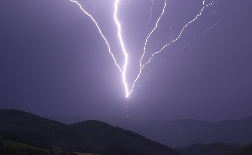
Lightning strike, TV tower
When lightning strikes the tower and knocks the transmitter off the air causing major damage and expensive repairs, that is a problem. When lightning strikes the tower and nothing happens, no problem. What is the difference between those two situations?
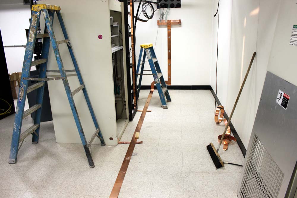
Grounding strap, FM transmitter site
If the generator starts and runs during every power outage and has done so for the last five years straight, it is obviously a reliable unit, does it need all that maintenance?
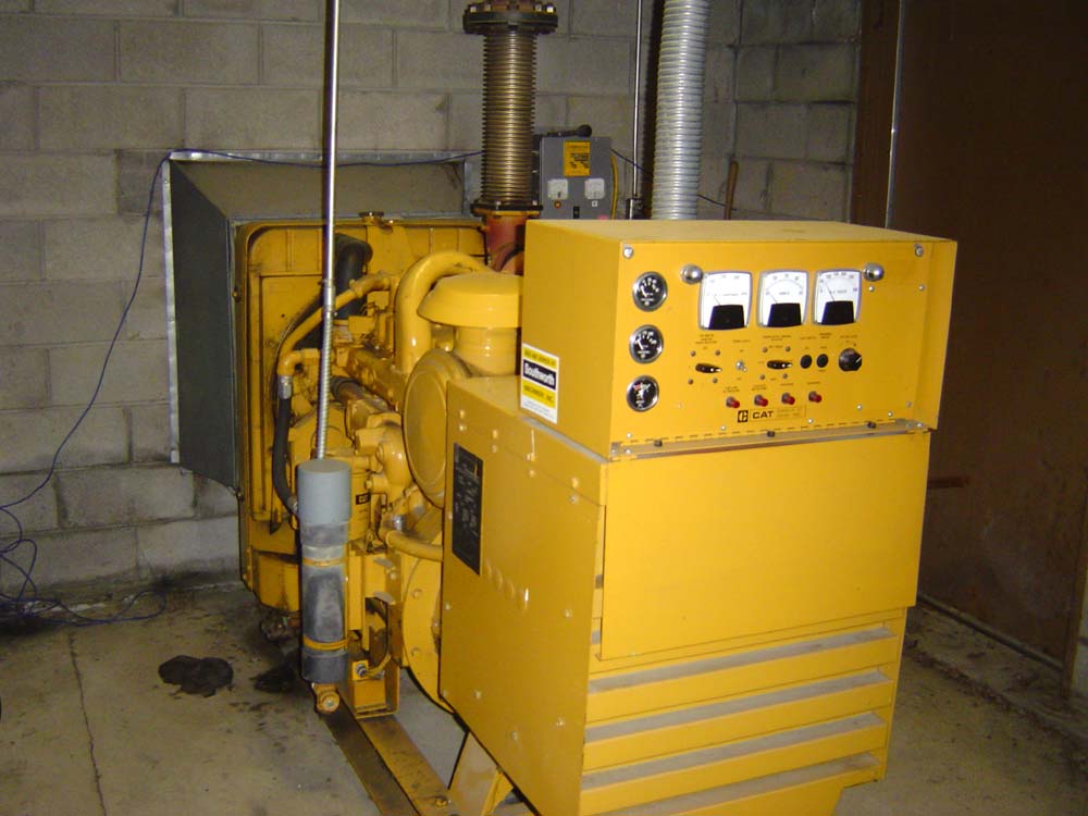
Caterpillar 75 KW diesel GENSET
Money spent on preventing undesirable outcomes can be difficult to quantify as disasters and events that do not happen are ill defined. It is difficult to quantify the “amount saved” on something that didn’t or won’t occur. Using past situations is good start, but that only covers a fraction of possible outcomes. In order to invest money wisely, one has to look at the probabilities. If there is an unlimited budget, then the probability exercise should be minimal, however, there is very seldom an unlimited budget.
For example, how much does a back up STL system cost vs the risk of being off the air while the main STL system is being repaired? How often do failures occur, when are they likely to occur and for how long are all good questions. Is there an alternative to a full backup like an IP CODEC? Such a solution would cover all aspects of the STL system including antennas, transmission line, transmitters and receivers.
There are certain FM stations north of here that have neither RADOMES or antenna heaters. Once every two years or so, the antenna ices up and the transmitter folds back due to VSWR. How much of an impact to listeners notice when this happens? If it happened more often, say two to three times a year, would it be wise to invest in some type of deicing equipment?
What is the ownership and management opinion on off air conditions? I have often heard tell “Oh, its only the AM, we don’t mind if it goes off the air.” That is, until it actually goes off the air, then it is a big problem.
Based on my and others experiences, these are the things that will happen at an average transmitter site:
The electricity will go off at least once per year for several hours.
The main transmitter will fail at least once every two years.
Lightning will strike the tower at least once per year.
The STL system will fail, at unknown intervals.
At studio sites, these things will occur:
The file server will crash depending on the operating system
The telephone lines and or T-1 service, internet service, ISDN etc will go out
The electric power will go out for several hours
The satellite dish will fail once every two to three years
If there is a tower, it will get struck by lightning
Other site specific things can occur like floods, blizzards, earthquakes, fire, etc.
Money spent on backup systems for those items is good insurance. Not only will the station stay on the air, the on call engineer’s phone will ring less often, which, if you are the on call engineer, should make you happy.
If a full backup is not available, a second transmitter for example, having a good stock of spare parts on hand can mean the difference between an early evening and an all nighter. Keeping good maintenance logs and well documented repair records can point out trends and give a good basis for ordering spare parts.
Repair trends are important. If the same part seems to be going bad over and over, it is time to dig deeper and find the cause of failure.
The old adage “An ounce of prevention is worth a pound of cure,” still holds true.
We are currently working with one of our clients who need to rebuild an FM transmitter site. The site is an old house that used to function as a studio. The transmitters are wedged into various places and the whole place looks like a fire trap. We are working on moving the transmitters to a new building at the base of the tower and installing all ancillary equipment according to good engineering standards.
The transmitter site design has changed somewhat over the years. What may have been good engineering standards in the past have changed with newer transmitter designs and needs. Up until about 1990 or so, most transmitter sites were cooled with outside air. As such, there was often a “filter room” or “air mixing room” with associated blowers and fans for moving air through the building. Older sites often had these features built-in as part of the transmitter installation. WPTR’s GE BTA-25 was a good example of this.
Modern solid-state transmitters are a little more delicate than their older tube-type brethren. Tubes were designed to run hot and had no trouble with temperatures up to 110 to 120 degrees or so. Continental transmitters were famous for this. As Fred Reilly once told me “We’re Dallas and it gets hot here. The manufacturing floor is not conditioned. It doesn’t matter, 100 degrees, 105 degrees, they just keep on working.” I think he was talking about the assemblers as well as the transmitters.
Solid-state transmitter switching power supplies are also somewhat finicky.
A good transmitter site design will incorporate the following:
Good air conditioning. Calculating the AC load for the transmitter waste heat, other installed equipment, as well as the building solar gain. Waste heat is a function of AC/RF transmitter efficiency, which is found in the owner’s manual. If unknown, 50% is a good design standard, in other words, waste heat equals TPO.
Good grounding. A good grounding system is a must for all transmitter sites. This includes lightning and RF grounds. Low impedance paths to a single point ground is a must.
Good power conditioning. Mountain top transmitter sites are susceptible to all sorts of utility company irregularities. Surge protection is a must. Series types are better than parallel.
Good lighting. Nothing is worst than fumbling around in a half-lit transmitter room trying to make repairs.
Adequate workspaces and clearances. Electric panels require three feet of clearance from the front. Cabinet doors should be able to swing fully open. All-access panels should be, well, accessible.
Adequate electrical system. Pole transformers and service entrances are properly sized for the load. Backup power. Plenty of work outlets around the room.
Some of these may seem like no-brainers, however, one would be surprised at how transmitter sites have grown over the years. An FM site that may have started with one 5 KW transmitter in 1950 will have been greatly upgraded over the years. Today, that same site may not employ a 30 KW transmitter, full air conditioning, several tower tenants, etc.
WHUD transmitter site diagram
This is a transmitter site that we redesigned about four years ago. The original site was built in 1958 and had a Gates FM5B as the main transmitter. The electrical service consisted of two 200 amp panels which had been greatly altered over the years. It had an old Onan 65 KW propane generator inside the building. Grounding, Air Conditioning, lighting, and workspace were all substandard.
The first thing we did was replace the generator with an outdoor unit. That allowed us to remove an interior partition, freeing up a good deal of floor space. The next thing we did was upgrade the electrical service and replace the generator transfer switch. Much of the interior wiring had been altered or added to in non-code-compliant ways. All of those modifications were removed or bought up to the current electrical code.
A safety grounding ring was installed around the outside of the building and all grounding points were bonded together. Nautel has an excellent guide for transmitter sites which includes lightning grounding and protection for AM and FM transmitter sites. Recommendations for Transmitter Site Preparation (.pdf) and Lightning Protection for Radio Transmitter Stations (.pdf) are available for download from their site. All RF cable outer jackets are bonded to the ground at the base of the tower and the entrance to the building. All the interior equipment is bonded together. Ferrite toroids are placed on all cables going into and coming out of the transmitter cabinets.
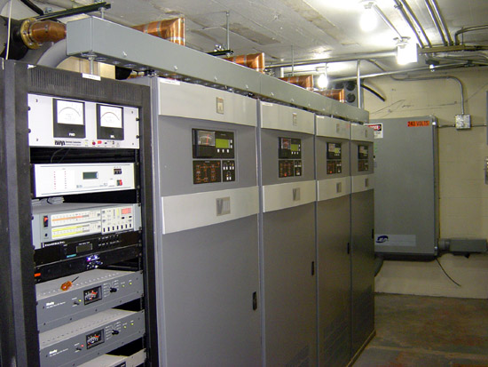
With the electrical service upgrade, we added the series LEA surge protector.
Inside view of LEA surge suppressor
This site as at the very end of the utility company line and has always suffered from power issues. This unit greatly smooths out the various nasties that get sent our way.
I decided that it was easier to use compact fluorescent lights (CFL) rather than long tubes. This site is as the top of a rough mountain road and it is simply easier to carry several small boxes in the cab of the truck than four foot or eight foot florescent light tubes. There is a total of ten 28-watt fixtures in the main transmitter room which light up every nook and cranny.
WHUD transmitter
All of the transmitters and electrical panels were laid out to give working room around them.
The air conditioners were also greatly upgraded and added to the generator load. Prior to this, when the power went out, which was often. the air conditioners did not run and the transmitter room would overheat unless the door was left open. What we previously the filter room became space for tenant equipment. There are a few two-way and paging companies still at this site.
Of course, all this work was done while keeping the station on the air as much as possible. There were a few instances of having to turn off to move transmission lines and so on.
The result of all this work is greatly improved site reliability.
If one considers paradise an FM35A. Going through another iteration of blown transmitter fuses for WEBE, Bridgeport, CT. Yesterday, I spent the afternoon examining the transmitter and found several interesting things:
Fresh arc tracks on the PA cavity and PA loading capacitor
The shoes and bars in the high-voltage contactor were severely pitted
One of the mains phases (middle) in the high voltage supply appears to be heating up, likely due to a loose connection.
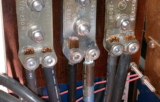
Discolored wire on buss bar
I checked and re-tightened all of the mains connections. Apparently, this is an old problem, as the Allen screw was tight. Interestingly, the fuse that was blown was on the red phase, which is different from what it was last time.
I spent the afternoon filing and sanding off the arc track marks in the PA cavity. It is very important to file flat all sharp points that were the result of arcing. Any sharp points will induce corona. I also filed down all of the contacts in a high voltage contactor, which took a fair amount of time. These are soft copper shoes and bars that had so much pitting and carbon I wonder how they didn’t catch on fire. I filed them flat. We were back on the 35A transmitter at full power by 4:30 pm.
If this happens again, I will bring my megger out and check the insulation on the wire between the disconnect switch and the HV power supply.
When I left the site at 5:30, I felt like we did some good work.