If one considers paradise an FM35A. Going through another iteration of blown transmitter fuses for WEBE, Bridgeport, CT. Yesterday, I spent the afternoon examining the transmitter and found several interesting things:
- Fresh arc tracks on the PA cavity and PA loading capacitor
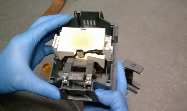
- The shoes and bars in the high-voltage contactor were severely pitted
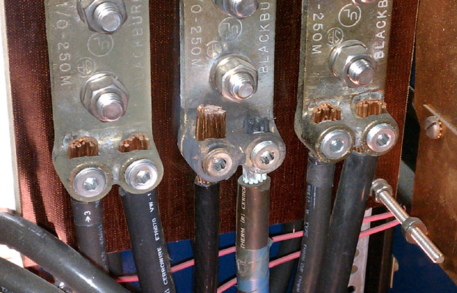
- One of the mains phases (middle) in the high voltage supply appears to be heating up, likely due to a loose connection.

I checked and re-tightened all of the mains connections. Apparently, this is an old problem, as the Allen screw was tight. Interestingly, the fuse that was blown was on the red phase, which is different from what it was last time.
I spent the afternoon filing and sanding off the arc track marks in the PA cavity. It is very important to file flat all sharp points that were the result of arcing. Any sharp points will induce corona. I also filed down all of the contacts in a high voltage contactor, which took a fair amount of time. These are soft copper shoes and bars that had so much pitting and carbon I wonder how they didn’t catch on fire. I filed them flat. We were back on the 35A transmitter at full power by 4:30 pm.
If this happens again, I will bring my megger out and check the insulation on the wire between the disconnect switch and the HV power supply.
When I left the site at 5:30, I felt like we did some good work.


The problems were much worse at the site back when they had less bays on the smokestack. I remember seeing the wall mounted surge protectors being blown off the wall and looking like they were victims of buckshot. While I personally did limited transmitter engineering there I do remember hearing multiple incidents of the contactor welding itself every time UI had a minor line surge. If I recall correctly I believe moving the power supply choke from the negative to the positive side cured most of the issues with both boxes down at the site. Mind you this is going back twenty-something years for me so it’s a little sketchy for me.
What I have found in my twenty three years taking care of those BE’s at that site is that you need to replace the main air filter every month and keep the transmitter clean be sure to turn off the high voltage before
removing the air filter because if you do not and a little
dirt gets in you will cause a arc in the final cavity
and melt the contactors together and blow the fuses.
I would also remove the lower back panel and clean
with a vac under the tube socket. The whole problem
with that site is the plate supply is running just
under 12kv around 11.86Kv due to the long run of transmission line and the antenna at 500 feet.
If you were to tap to a lower plate voltage your
current would go high and your tube life would not
be very good and your efficiency would go down.
As you can see on the tube chimmney I have sprayed
them with high voltage paint about six time to help
cut down on the arching. I also had BE to the site to install the larger chimmney and tunning sections on both of those BE transmitters. In general the transmitters ran well
I would rotate every six months between transmitters.
The bigest problem I always had was the air conditioners
thermostats sticking, units freezing up. I just could not
Convince management/owners to upgrade to central AC’s for that site.
One more thing I forgot in my long last post.
A additional cap was added to the high voltage supply
on both transmitters to help smooth things out.
It has never been a easy site to keep running.
Ed, I think the main issue with that site is the mercury laden dust from the coal fired power plant. I’ve worked on may a transmitter with 12, 14 and even 25KV B+. It is true they need to be kept clean, but this transmitter was not dirty when it arced. The AC’s also need to be replaced with large commercial 3 phase units.