Medium Frequency ATU design

This is a topic I have covered before, but it is worth doing it again for future reference.  The previous post covered downgrading an AM transmission facility for WGHQ, Kingston, NY.

This is part II of that process.

WGHQ transmitter site, towers 1 and 2 removed

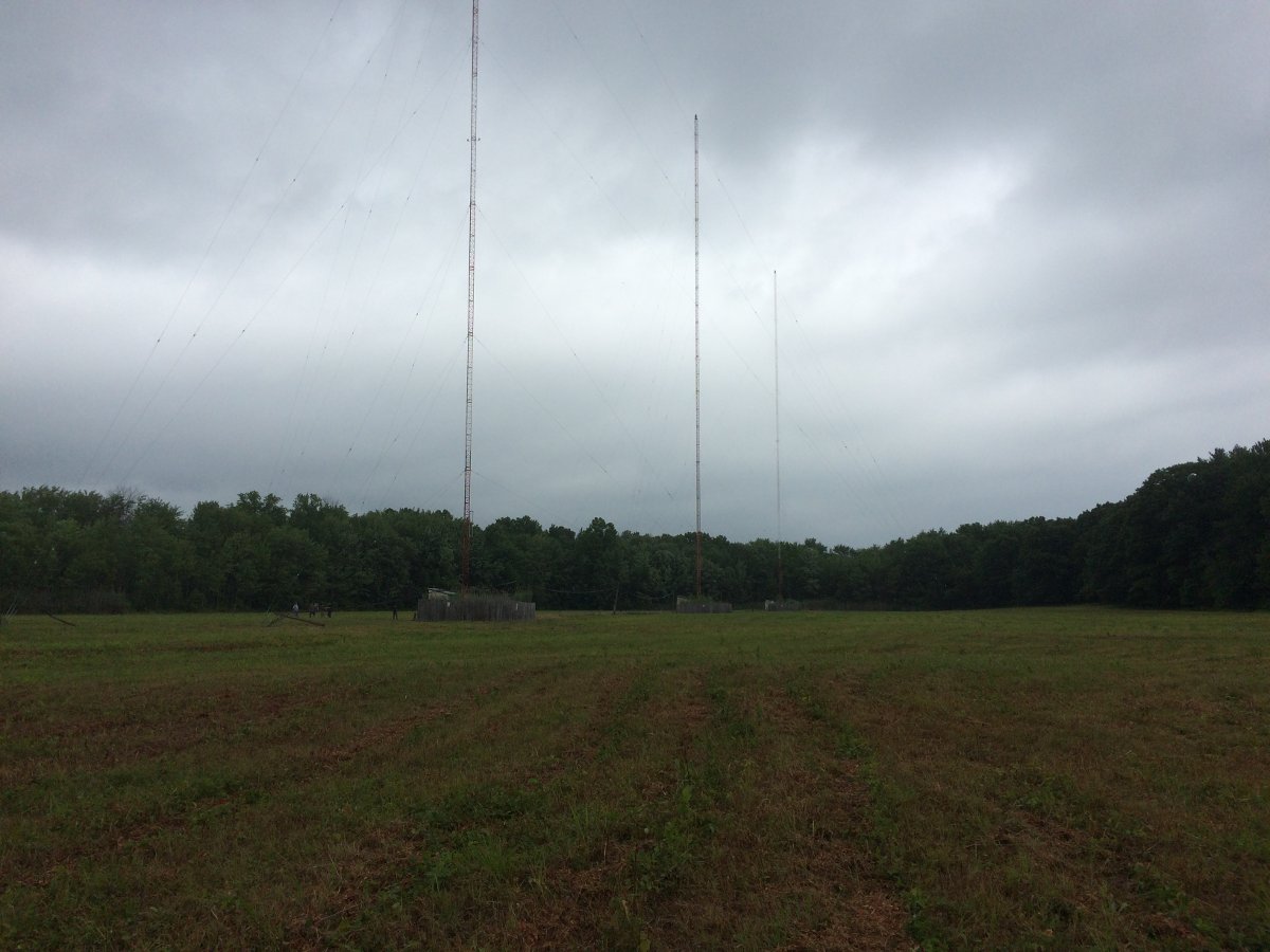
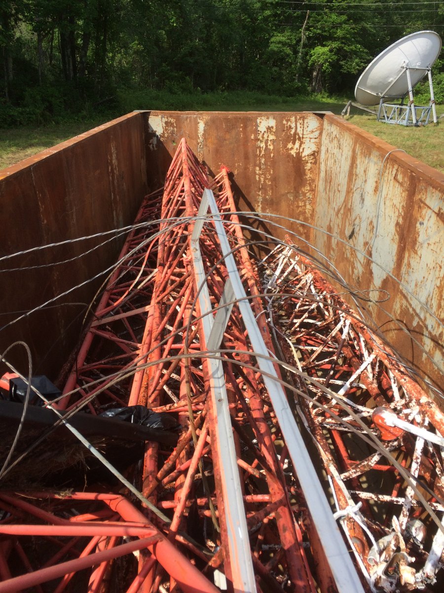
The old towers have been cut up and put in a scrap metal dumpster. They are off to China to be melted down and made into a submarine or a missile or a tank or something useful like that.

Towers scrapped
Towers scrapped

The directional array had three towers in a straight line with a common point impedance of 60 Ohms.  Dropping two towers greatly changed the electrical characteristics of the remaining tower, therefore the existing ATU needed a bit of reworking to match the 50 Ohm transmitter output.

The first step, correct a few deficiencies left over from the old array.

Vise grip tower feed

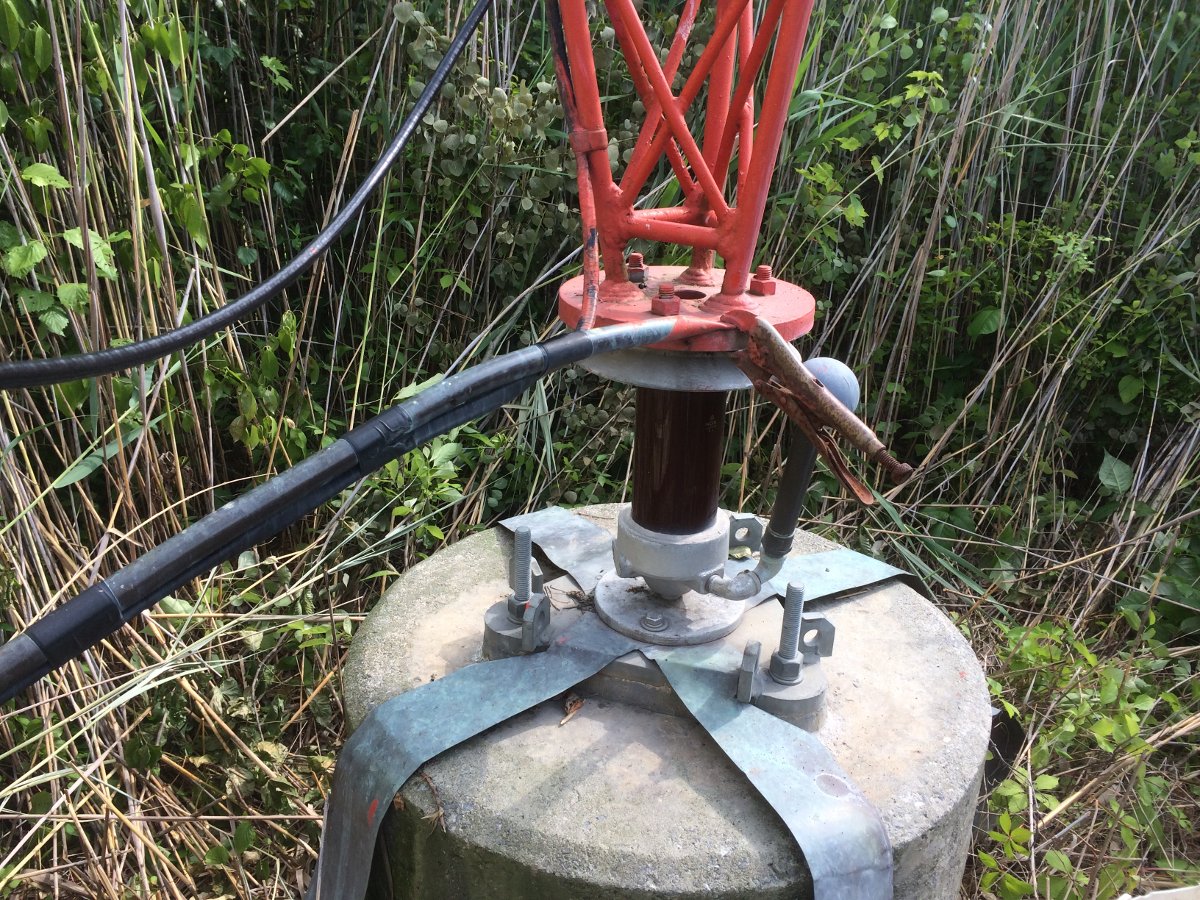
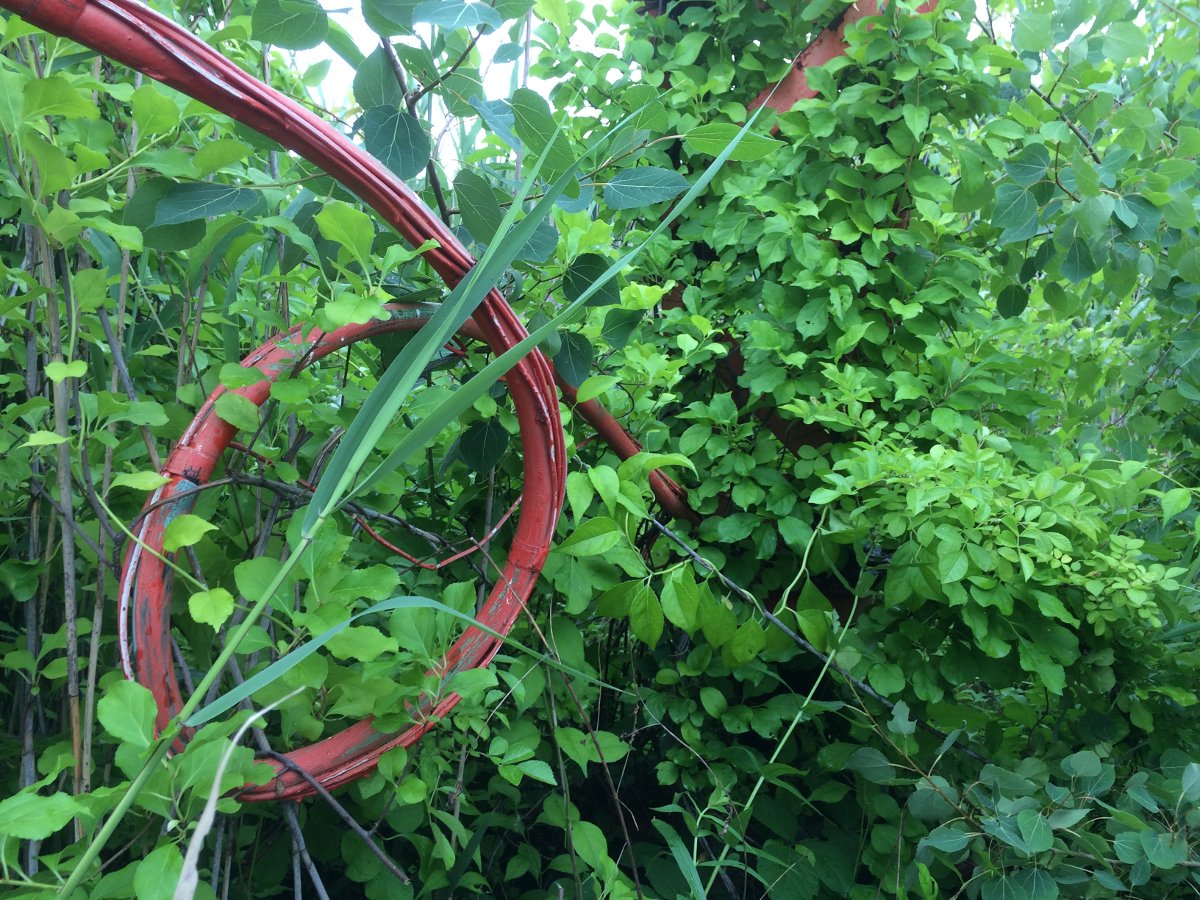
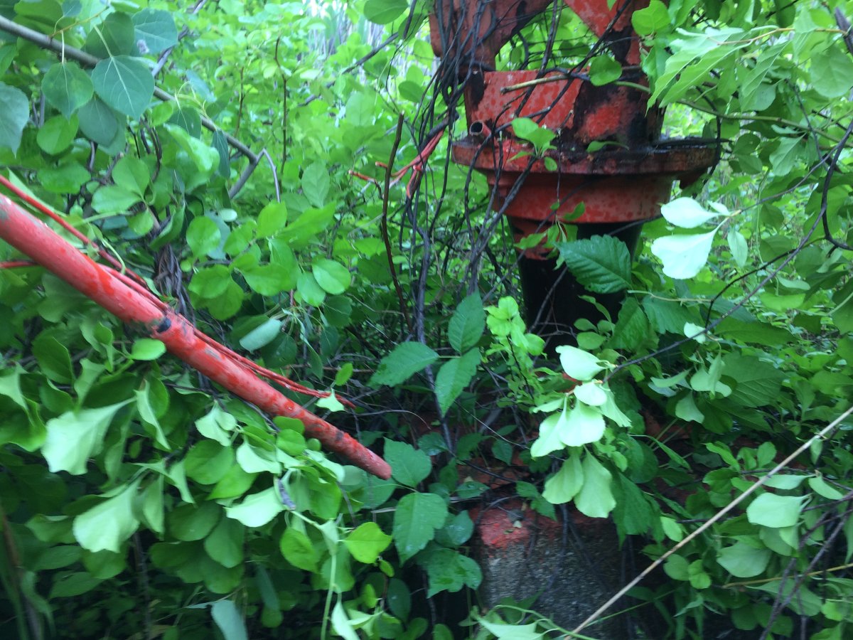
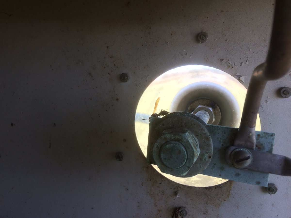
This vise-grip RF connection has to go. The problem is where the tower erectors attempted to solder the copper tubing.  That tower base plate is pretty big and I would wager they didn’t use enough heat to make the solder connection.  They were probably working in the winter time, thus the “temporary” fix.  This tower was put up in 1993, so that temporary fix lasted 23 years.

I removed the offending tool and soldered the connection to another part of the tower with silver solder.  The smaller crossbar made a good connection point.

RF feed correctly connected to the tower

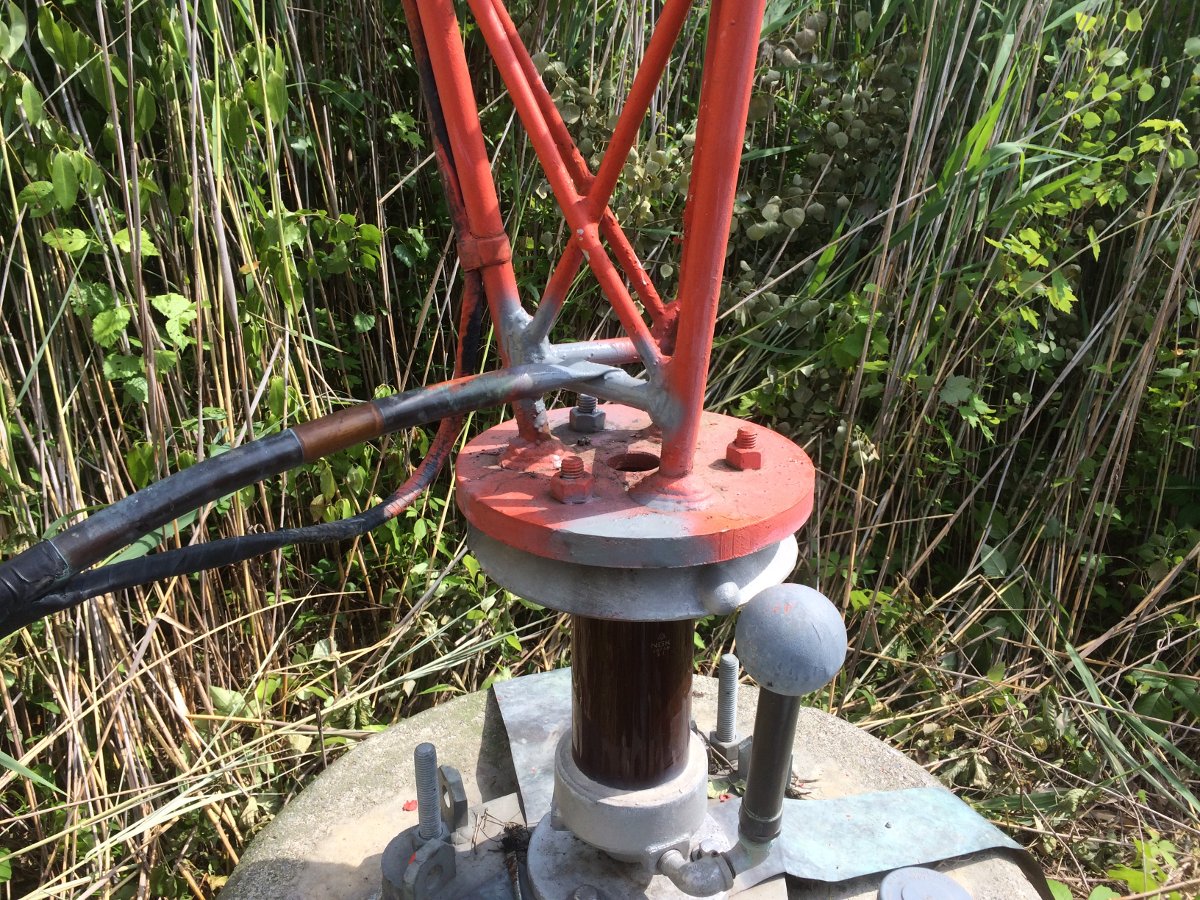
After soldering, I cleaned up and sprayed some grey primer on it to prevent rust from forming where I scraped the paint off.

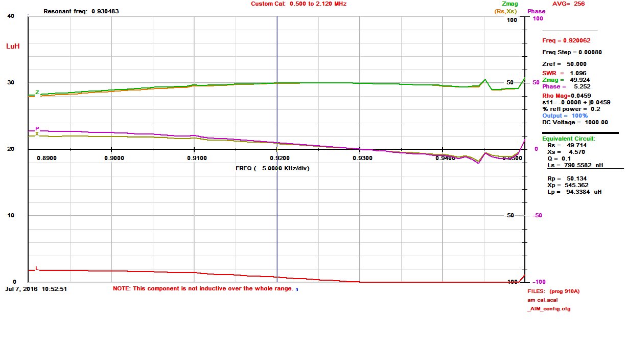
Next, I made an impedance measurement:

WGHQ tower base impedance measurement
WGHQ 920 KHz tower base impedance measurement

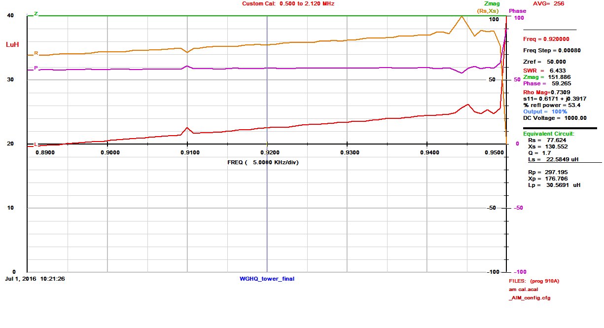
That junk on the upper part of the graph is coming from WHVW on 950 KHz. The tower itself looks pretty good, 77.6 Ohms resistance with 130 Ohms inductive reactance.  Since this is not part of a directional antenna system, the ATU design is pretty straightforward.  Given that WHVW on 950 KHz is located 10.41 miles away, a low-pass filter design is optimum.  A basic low pass filter T network has inductive input and output legs with a capacitive shunt leg to ground.

T network diagram
T network diagram

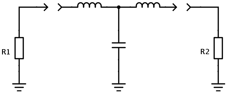
Each leg is used to match the 50 Ohm transmission line impedance (R1) to the 77.6 Ohm tower impedance (R2) and cancel out the 130 Ohms of inductive reactance.  This is a vector impedance problem, much like a vector force problem in physics.   Some basic arithmetic is required (always include the units):

X1, X2, X3 = √(Zin x Zout)

X1, X2, X3 = √(50Ω x 77.6Ω) or X = 62.28Ω

The value of inductance or capacitance for each leg is calculated using the basic inductance or capacitance formulas:

L (μH) = XL / 2πf(MHz)

And

C (μF) = 1 / 2πf(MHz) XC

Thus the input leg, or X1 = 62.28Ω / (6.28 x 0.92 MHz) or 10.78 μH

The Shunt leg, or X2 = 1 / (6.28 x 0.92 MHz x 62.28Ω) or .0028 μF

The output leg is a little different.  The tower has 130 Ohms of inductive reactance that needs to be canceled out with a capacitor.  Rather than cancel out all of the inductive reactance, then add an inductive output leg, the tower reactance can be used as part of the tuning circuit.  The design calls for 62.28 Ohms inductive reactance, so 130Ω – 62.28Ω = 67.27Ω, which is the value needed to be canceled by a capacitor:

Output leg, or X3 = 1 / (6.28 x 0.92 MHz x 67.27Ω) or .0025 μF

A little Ohm’s law is used to calculate the base current for both the day and night time operations.

Ohm's law pie chart calculator
Ohm’s law pie chart calculator

Thus the daytime base current is I = √(P/R) or I = √(1000 W/77.6Ω) or 3.58 Amps.

Night time base current is I = √(38 W/77.6Ω) or 0.70 Amps

Current handling requirements:

Base current is calculated to be 3.6 Amps at 1,000 Watts carrier power.  Allowing for 125% peak positive modulation makes it 5.7 Amps.  Having a safety factor of two or 11.4 Amps output leg and 14 Amps input leg.

Voltages: 353 maximum input voltage, 439 output.

Thus, 20 amp, 10 KV parts should work well.

The designed schematic for the ATU:

WGHQ ATU Schematic diagram

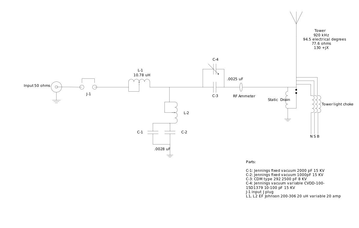
Putting it all together.

Since the tower looks fairly broad at 920 KHz, we are going to attempt a nice broadband ATU to match it.  This station is currently programmed with a classic country format, and I have to tell you; those old Conway Twitty, Merle Haggard, Patsy Cline, et al., songs sound pretty good on the old AM radio.  The Subaru stock radio has HD, which also has a nice broad IF section, thus allowing all those lovely mid-high-range frequencies through.

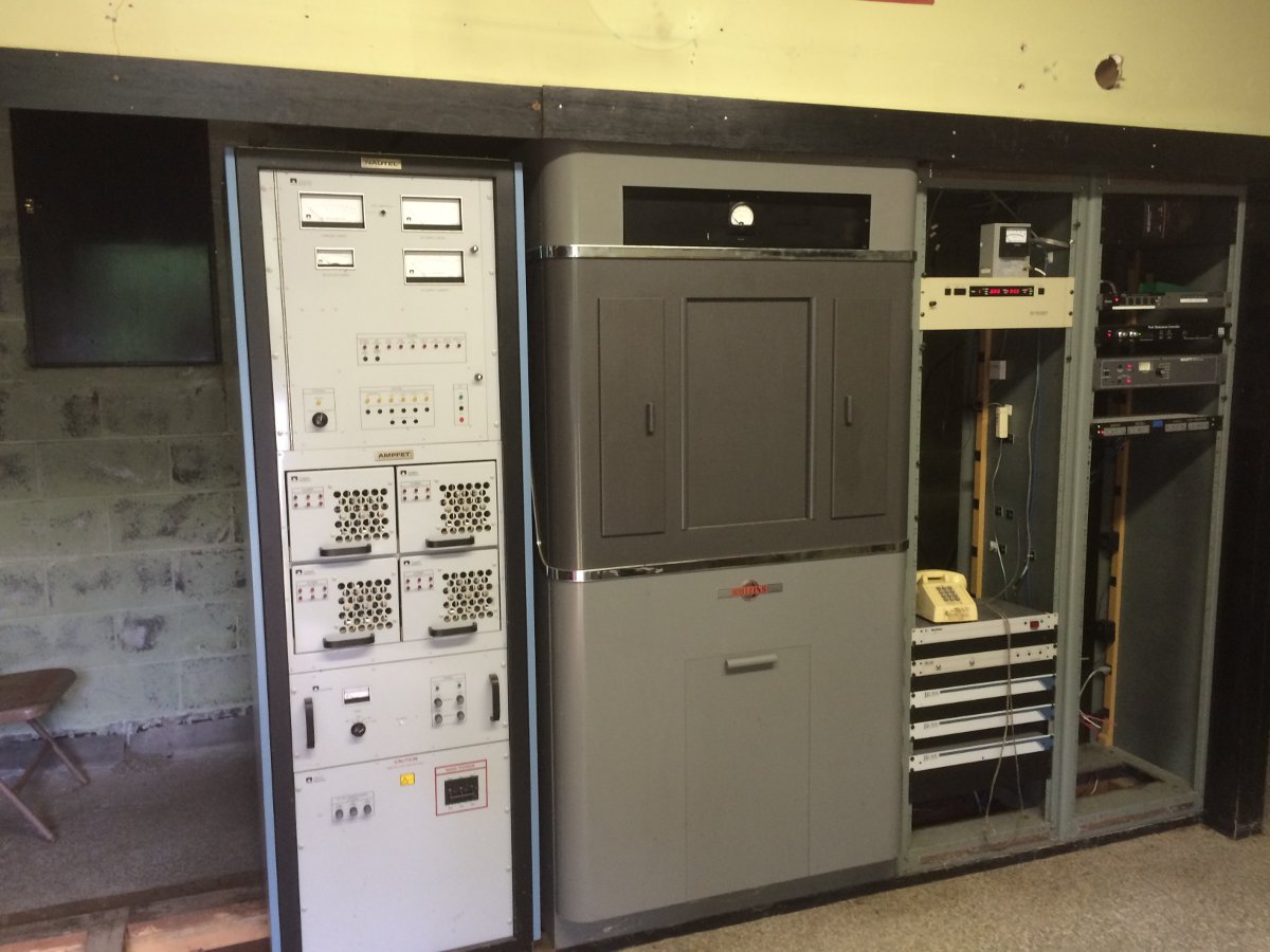
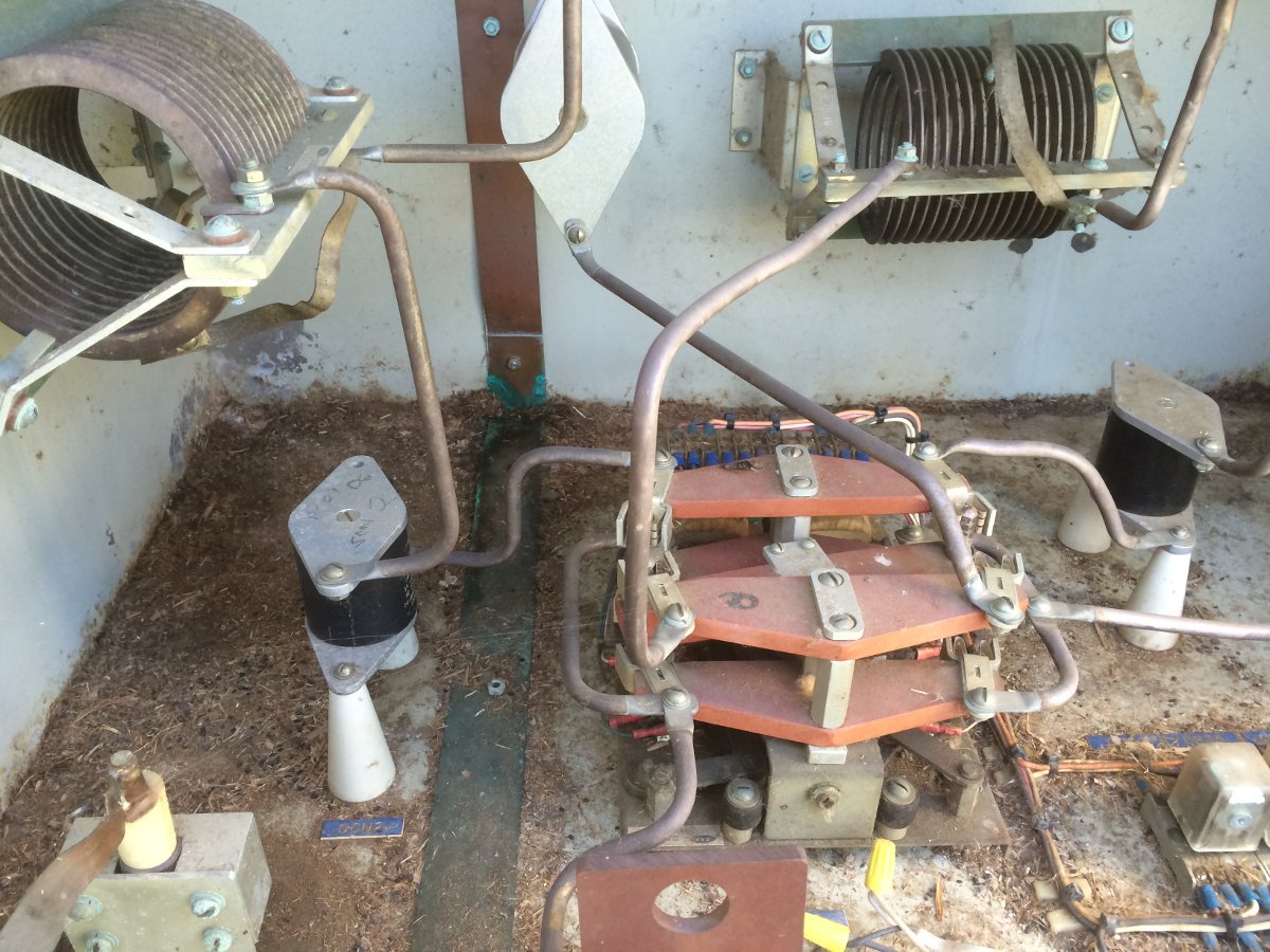
This is the existing ATU, which I believe was built by Collins in 1960:

WGHQ Tower 3 ATU
Existing WGHQ T network ATU

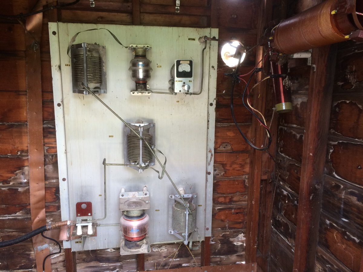
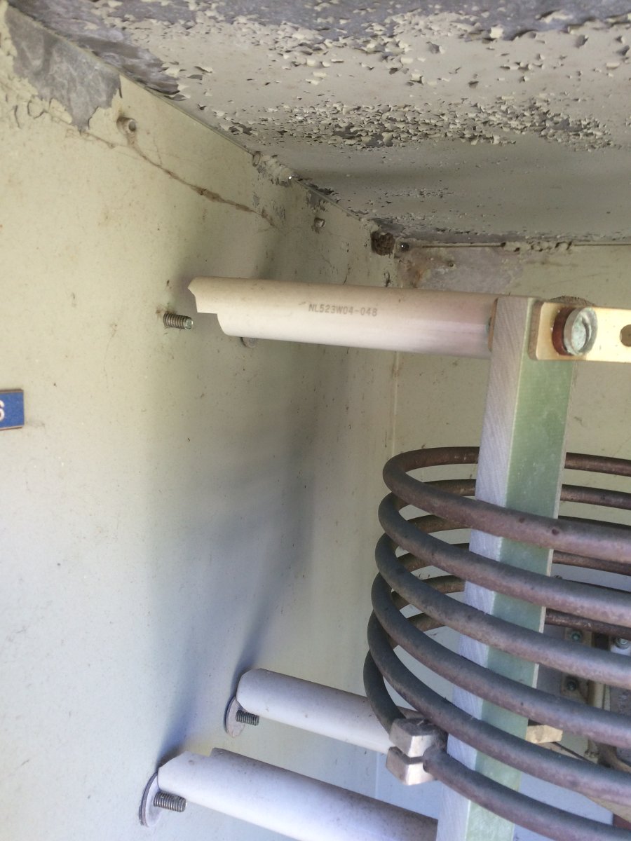
The ATU building is a little rough, but the ATU itself is in remarkable shape for being 56 years old.  The input leg inductor is in the center and will be reused as is. The large Jennings vacuum capacitor at the bottom is a part of the shut leg.  Its value is 2000 pF at 15 KV.  The top vacuum capacitor is a series output cap, its value is 1000 pF at 15 KV.  The basic plan is to move the upper cap down in parallel with the bottom cap.  The shut leg inductor will be kept in place to tune out any access capacity.  For the output leg, I have a 2500 pF mica cap and a 10-100 pF variable cap connected in parallel.  The inductor on the output leg will be removed.

After some re-work on the ATU components, I tuned everything up.  The easiest way to do this is to disconnect the legs, measure them individually, and adjust them for the desired reactance, which in this case is 62.28 ohms or thereabouts.  The output leg was measured with the tower connected since the tower reactance is a part of the tuning circuit.  The input leg was right about 10 μH.  The shunt leg turned out to be about 0.002 μF.  This is often the case, theoretical values are slightly different than field values due to stray capacitance and inductance in the connecting straps, etc.

This is the load, as measured at the output terminals on the transmitter:

WGHQ tower load as measured at the transmitter output terminals

Slightly asymmetric on 910 KHz, but overall pretty good. There is a fair amount of phase rotation in the transmission line due to the length from transmitter to the tower (855 feet, 260.6 meter), which works out to be 0.93 wavelength allowing for the 86% velocity factor of the transmission line.

Time to pack up and go home.

Downgrading an AM radio station

WGHQ in Kingston, NY has been downgraded from a 5KW DA-1 to a 1KW non-DA system.  This was done because two of the three towers in the directional antenna array dated from 1960, were in very rough condition and needed to be replaced.  The remaining tower (furthest from the transmitter building) had been replaced in 1994, is in good condition, and is being kept as the non-directional radiator.

Here are a few pictures:

WGHQ 3 tower directional antenna array, Port Ewen, NY
More deferred maintenance
RF and tower light feed disconnected from tower base
Second tower base vegetation not as bad, tower disconnected
WGHQ transmitter and original Collins phasing cabinet

First tower video (sorry, I appear to have no idea what I am doing with the camera):

Second tower video, this one is better:

Towers on the ground:

I made measurements on the third tower and constructed a temporary ATU with parts on hand to get the station back on the air. They are now running 1 KW day, 38 watts night, as per their CP. I will be going back up to finish the job once the brush has been removed from around the existing tower and the ATU building has been repaired.  The coverage with 1 KW is not bad, actually:

Predicted coverage map from FCC website

The translator is on the way.

The inglorious task of AM antenna array maintenance

AM radio stations are rough customers. They frequently operate on the margins, both in terms of ratings and revenue. Their transmitter plants are complex and very often have been on a reduced maintenance schedule for years, sometimes decades.  Those of us that understand the operation of AM transmitter plants and all their quirky behaviors are getting older.  I myself, feel less inclined to drop everything and run off to the AM transmitter site when things go awry.  Seldom are such efforts rewarded, much less acknowledged.  Station owners are also finding that their previous demands are unrealistic.  For example, time was that any work that takes the station off the air had to be done after midnight.  These days, I can tell you, I will not be working at your radio station after midnight.  You can find somebody else to do that work.

Thus, today, we took this particular AM station off the air from Noon until 3 pm to diagnose and repair a problem with the four-tower daytime array.  Once again, this involved a shift in common point impedance and a drastic change in one tower’s current ratios.

Antenna Tuning Unit, mice have made a mess

In all fairness to the current owner, this ATU reflects years of neglect. At some point, mice made a home in there and created a mess. The ATU smells of mouse shit, piss, and mothballs.  It is full of mouse droppings, grass seeds, and fur.  All of the ATUs in this array are in similar condition.

Paper wasp, inside ATU

It was warm enough that the wasps were active, if not a little bit lethargic.

Broken stand off insulators in ATU
Broken stand-off insulators in ATU

This coil is being held up by the tubing that connects it to other components. When the ATU was built, no nylon or cork bushings were used between the insulators and the wall of the ATU they were mounted on. Heat cycling eventually did all of the insulators in.

Catwalk to the other towers

Catwalks to the other towers. At least the swamp grass has been cut this year, it is only four feet tall instead of ten.

Tower base
Tower base

The tower bases are all elevated above the theoretical maximum water level. The ATUs are also up on stands with platforms build for maintenance access.

ATU Work "platform"
ATU Work “platform”

I cannot even blame the current owner, who has to spend considerable money to make repairs and upgrades to this site. It is very difficult and very expensive to catch up with deferred maintenance. Sadly, most AM stations we encounter have similar or worse problems.

I think it is too late to save many of these AM stations.  The technical issues, lack of revenue, perceived poor quality, and lack of good programming are all taking their toll.  At this point, the hole is so deep there is no hope of ever getting out.  The FCC’s faux interest in “revitalization” followed by two years of stony indifference seems to be a final, cruel joke.

Installation Check Lists

On the subject of project management; oftentimes, we need to keep track of the small details that can derail a project, blow the budget, and upset schedules. A quick checklist can help to identify things that might not have been planned for. I developed a checklist mentality in the military. There, we had checklists for everything. Simple day-to-day things like disposing of garbage over the side, or pumping the CHT (sewage) tank to complex evolutions like entering or leaving port all had a checklist.  On the aforementioned CHT tank; the Coast Guard cutter I was on had a vacuum flush system to conserve water.  Emptying the CHT tank involved a complex set of valve openings and closings to route compressed air into the vacuum tank and literally blow the sewage overboard.  Anyone can see the danger in such a design.  Failure to follow the exact procedure resulted in raw sewage blowing out of the nearest toilets, which were unfortunately (or perhaps humorously) in the lower-level officer’s staterooms.

But I digress.

I have made a series of outlines for different project types.  These can be used as general guidelines for project planning and management.  Of course, each project is different, but these are flexible enough that they can be adapted on a project-by-project basis.

These are for general use and should be adapted for your own purposes.  Don’t forget to document and label all the wire runs, etc.

Also, do not forget the transmitter site maintenance checklists: FM transmitter site maintenance list, AM transmitter site maintenance list. I have used these reliably at many different sites since I committed them to writing in late 1999.