WKIP

This was the radio station that I listened to (or rather, my parents listened to) when I was a very young kid.  From this source, things like school closings, weather, lunar landings, news, sports and traffic could be heard.  At one point, there was a guy called the “Traffic Hawk,” (real name Don Foster) who flew in a Cessna 172 east and west over main street in Poughkeepsie advising drivers of any slow downs in the area.  That’s right, Poughkeepsie, New York, population 30,000, had it’s own eye in the sky, broadcasting live from the aircraft overhead.  Actually, I think he also flew up and down South Road (US Route 9) in the vicinity of the IBM plant, which employed quite a few people in those days.

There was also a guy who tried to break the Guinness Book of World Records by staying awake the longest, this happened several times.

For me, it was the school closings.  I hated school with an absolute passion.  Everyday, I would ride the school bus and say a little prayer; “…please God, make it today.  Make the boiler stop working, or the electricity go out.  Make the kitchen catch on fire or the roof cave in.  You are a great and mighty God and I don’t ask for much.  Please destroy my school today.”  Alas, God did not seem interested in this.

Anyway, back to the topic at hand.

WKIP first signed on in 1940 with the studios and transmitter located at The Nelson House, 42 Market Street, Poughkeepsie.  That building is long gone and the location appears to be the parking lot for the Dutchess County Office building.  Being neighbors with some influential guy from Hyde Park made for a nice dedication speech:

It signed on with a power of 250 watts on 1,420 KC on June 6th, 1940. Soon thereafter, it changed frequency to 1,450 KC as a part of the AM band shift brought about by NARBA.

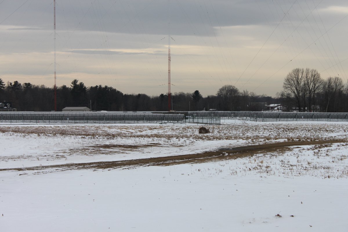
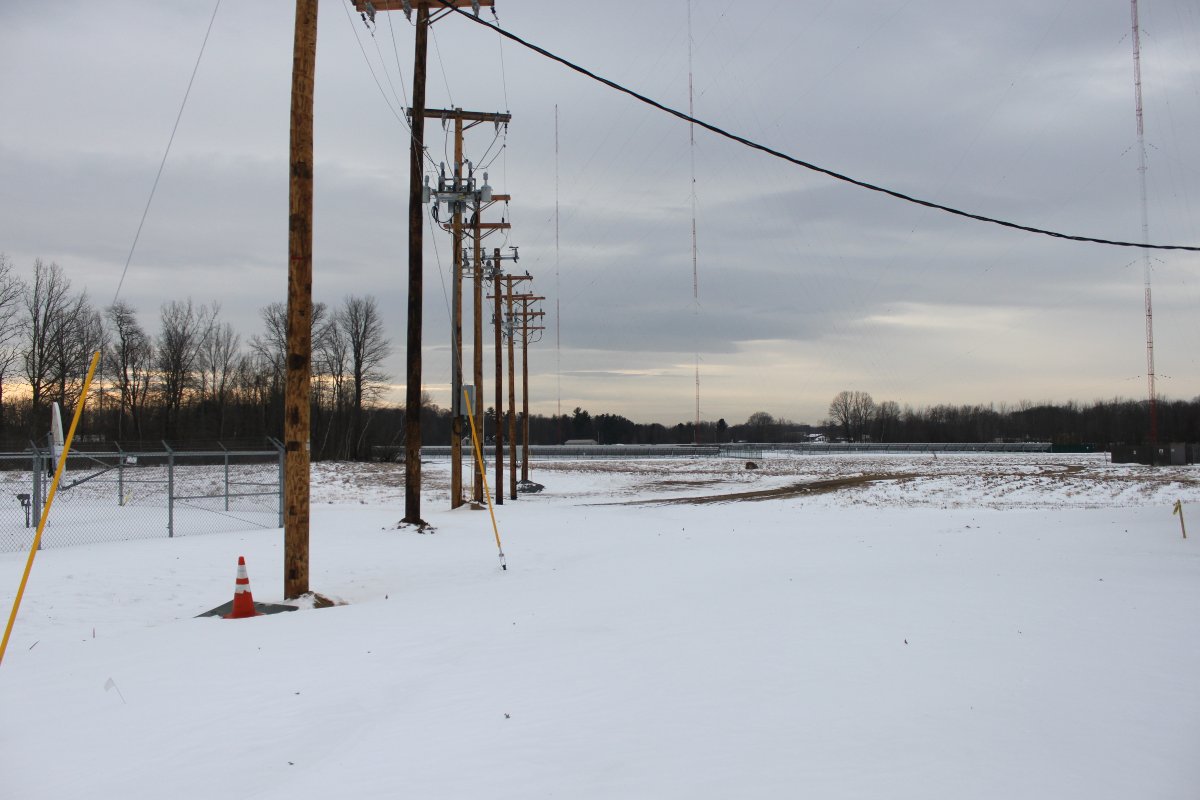
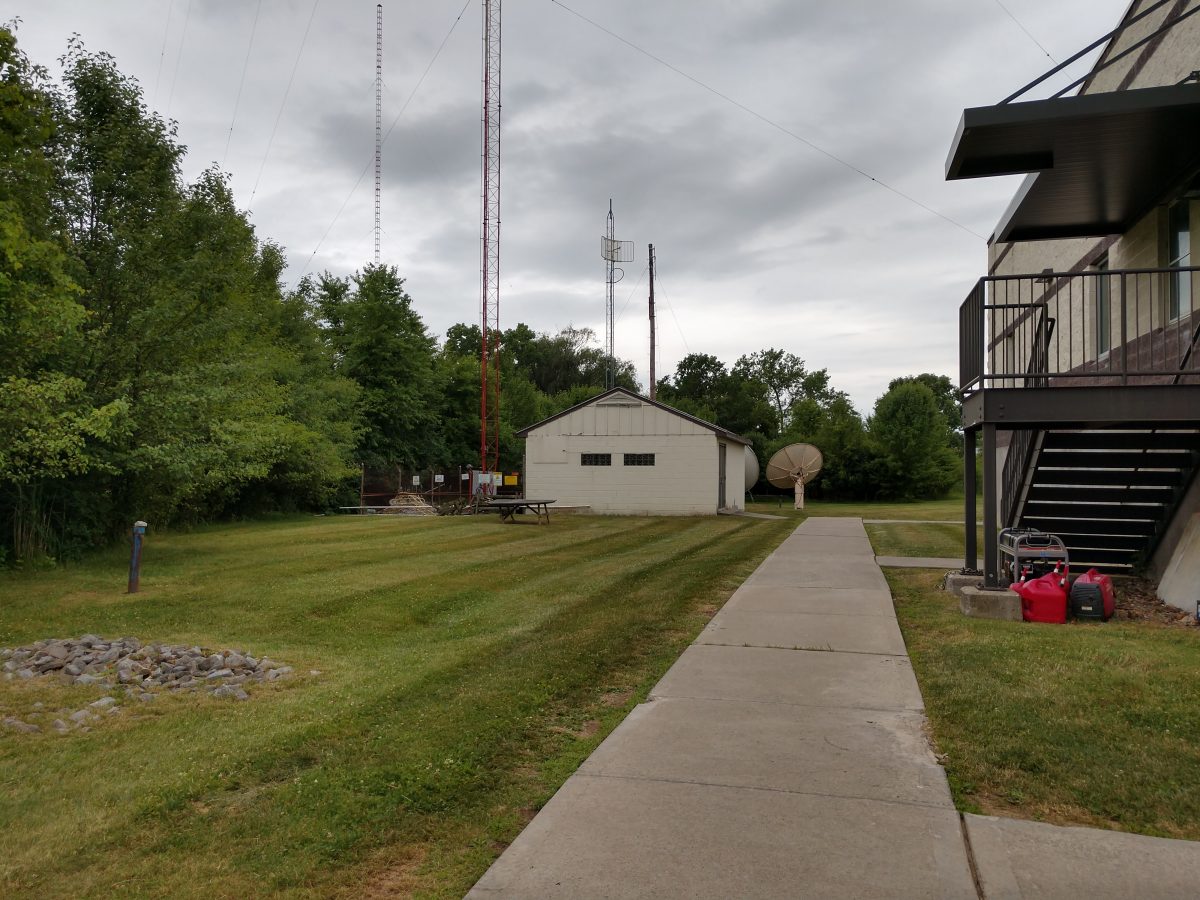
Over the years, the station went through several ownership changes. The first major technical change came in 1961, when the station transmitter site moved to its current location, then called Van Wagoner Road, now Tucker Drive. The station increased power to 1,000 Watts and installed a directional antenna for daytime use.  It is one of those rare nighttime non-directional, daytime directional stations.

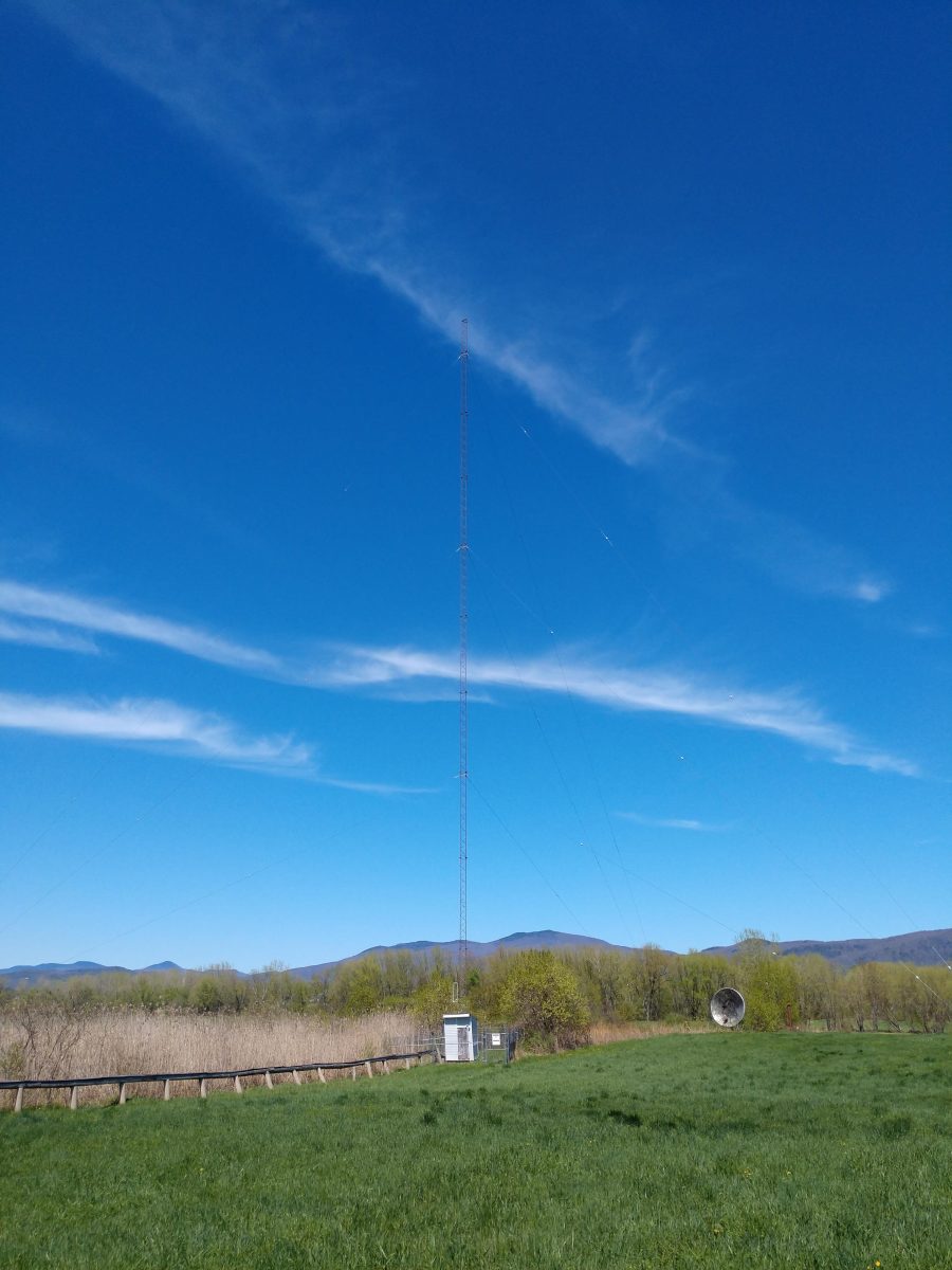
The directional antenna consists of two towers; tower one is 180 degrees tall (103.4 Meters or 340 feet) with 35 degrees of top loading.  That is used for both the day and nighttime array.  Tower two is 85 degrees tall (48.8 Meters or 160 feet) and is used only for the daytime array.  This pushes the major lobe of radiation towards the north.  I don’t know the reasoning behind that, but somebody spends a good amount of money to make it so.

Here is an air check from the early 1980s.  Weather on that day was “Sunny, cloudy, whatever… take your pick.”

Good old Steve Diner.

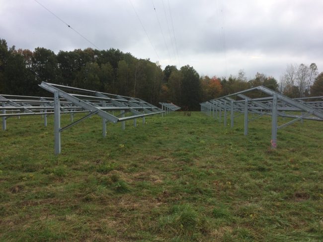
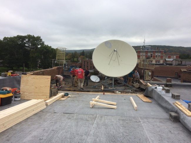
Today, the station looks like this:

The 1961 WKIP transmitter building with tower

When I was growing up, my cousins lived within walking distance of this. We used to come over and throw rocks at the tower when the station was unmanned on Saturdays and Sundays. At least, I think it was unmanned because no one ever came out and yelled at us.

WKIP backup transmitter, phasor and main transmitter

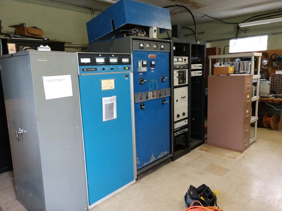
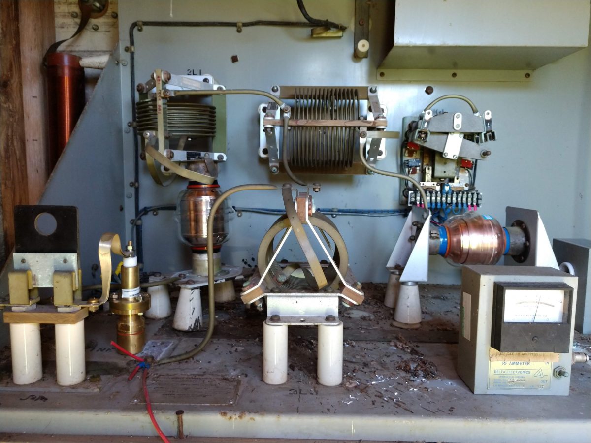
Mid-1980s MW-1A still runs. The BE AM1A is the main transmitter. The phasor is the Original 1960s Gates Phasor.

This video shows how the studios used to look before they were rebuilt by Clear Channel Circa 2002 or so. At about the 2:02 mark, you will see the room pictured above as it looked in 1990.

The space between the video above and the picture below looked bad with nothing in it. It looks better now.

WKIP clock
WKIP clock

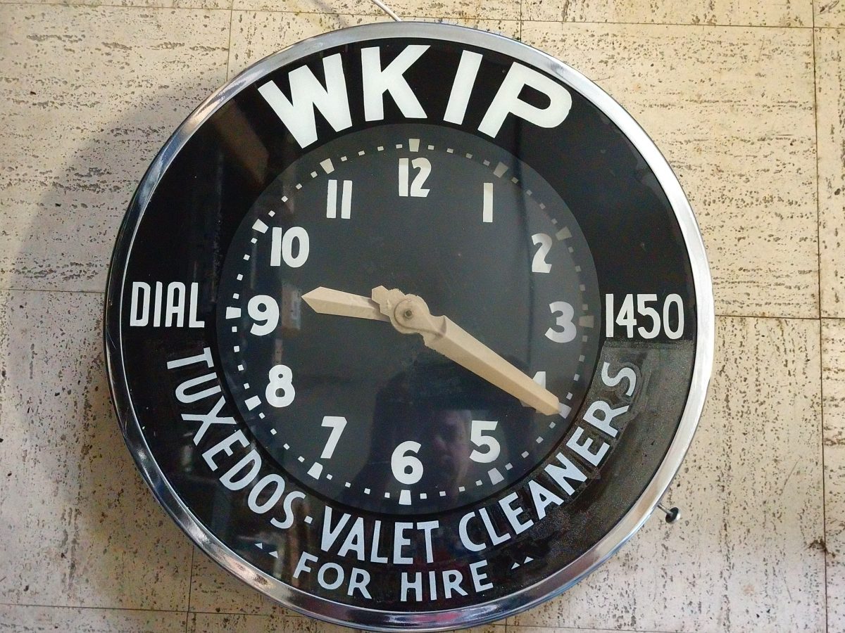
That clock is a collector’s item and belongs in a museum.

AM station downgrade

I have been working on another formerly directional class B AM station, this one is in Rutland, VT.  WSYB has been on the air since 1931 with the same call letters serving the east-central part of Vermont.  In 1931, it was operating on 1500 kc with 100 watts of power.  In March 1941 it moved to 1490 kc with 250 watts before settling, a few months later, on 1380 with 1,000 watts, directional night time protecting CKPC in Brantford, Ontario, Canada.

The transmitter site was first located at 80 West Street (now known as BUS US 4), in Rutland.  It was moved to its current Dorr Drive (Formerly Creek Road) location in 1938, when the station was requesting a power upgrade to 250 watts.  Whilst cleaning out the old transmitter building, a copy of an operating log, dated December 7, 1945 was discovered in the attic above the transmitter room:

WSYB transmitter log, 1945

Back from the time when readings were required every 30 minutes.

In 1956, WSYB was allowed 5,000 watts daytime non-directional with 1,000 watts nighttime directional.

At some point in the early 1990s, the original towers were replaced with solid-leg Pirod towers, each 195 feet tall.

After that, things went the way things do; AM steadily declined in favor of FM, local programming was mostly replaced by syndicated satellite stuff, there were several transfers of ownership, etc.

A translator on 100.1 MHz was added in 2016; the two-bay Shively antenna was installed at the top of the South West tower.   There is local programming on the station from 6 am to noon on weekdays.  There may also be some gardening shows and other such programming on weekends.

The current owner has decided like they have done in other markets, that AM directional antenna systems are a maintenance nightmare, the risk of FCC sanctions are high for an out-of-tolerance antenna array, and the ratings and income from the station do not justify the risk/cost.  Thus, non-directional nighttime operation was applied for and granted.  The station is now a Class D with 25 ass-kickin’ nighttime watts.

WSYB had a two-tower nighttime antenna system.  The tower closest to the building (SW) was also the daytime, non-directional tower and it now holds the FM translator antenna and STL antenna.  Thus, it was decided to ground that tower and keep those antennas in service.  The far tower (NE), which was the second tower of the nighttime array would become the AM antenna.  The nighttime ATU was built for less than 1,000 watts of input power, so several components needed to be upgraded for 5,000-watt operation.

WSYB rebuilt ATU
WSYB rebuilt ATU

I had available these nice vacuum capacitors that came out of another decommissioned antenna system.  The vacuum capacitors are great because the voltage/current ratings are much higher than the mica capacitors that were in the circuit before.  You can see black goop where one of the Sangamo mica capacitors on the input leg failed several years ago.  These vacuum capacitors are rated at 15 KV and the current rating at 1.38 MHz is probably in the 70-80 amp range.  I had to move the base current meter from the former daytime (SW) tower out to the NE tower.  The day-night switch was taken out of the circuit.  The transmission line to the far tower was replaced with 7/8 inch foam dielectric cable.  A slight touch-up of the coil on the input leg of the T network was all that was required to bring it into tune.

The electric lines to the tower have been temporarily disconnected.  As soon as they are reconnected, I will vacuum out all the mouse crap and other debris.  The ATU building also needs some work sealing it up against the elements.

The tower base impedance is 75 ohms, +j95 making the base current 8.6 amps daytime and 0.58 amps night time.

WSYB radiating element

For me, the magic of radio exists at that boundary between the real objects (towers and antennas) and the ether.  The transference of electrical voltages and currents into the magnetosphere is something that still fascinates me to this day.  Coupling a 5,000-watt medium wave transmitter to a tower and watching it work is something that I will never grow tired of.

Happy New Year!

After a bit of reflection and a few good conversations over the New Year’s Holiday, I decided that I should continue my work on this blog.  I would like to thank all those that have stuck by and waited.  I have received numerous emails and messages offline, all of which have been read and appreciated.

Since the abrupt stoppage last July, which was absolutely necessary for me, many things have happened within the business.  Fortunately, during the hiatus, I was still taking pictures.  After sorting through them, here are a few interesting things that happened:

At one of our client’s AM transmitter sites in Albany, NY a 2.6 Million Watt solar system has been installed.

WROW-AM Steel mounting poles on antenna array field

This project required many steel mounting posts to be driven into the ground around the AM towers.  I don’t even know how many, but I would hazard a guess of over three hundred.  Each one of those mounting posts was hand-dug down a depth of 6-10 inches to look for ground wires.  Where ever a ground wire was found, it was moved out of the way before the post was set.

WROW-AM ground wire moved out of way

Basically, the solar array covers about 1/2 of the antenna array field.  All of the steel mounting hardware is tied into the ground system, making, what I am sure is a pretty large above-ground counterpoise.

WROW-AM solar panel mounting hardware

View from the south looking north:

Solar Array installed on WROW antenna array, Glenmont, NY

View from the north, outside of the transmitter building, looking south:

Solar Array installed on WROW antenna array, Glenmont, NY

Power company interface and disconnect:

Solar Array utility company disconnect, Glenmont, NY

The utility company had to upgrade the transmission lines to the nearest substation to handle the additional power produced by the solar system. All in all, it was a fun project to watch happen.

At a certain studio building, which is over 150 years old, the roof needed to be replaced.  This required that the 3.2-meter satellite dish and non-penetrating roof mount be moved out of the way while that section of the roof was worked on.

3.2 meter satellite dish

Dish was ready to move, and all of the concrete ballast was removed and taken down from the roof.  The roofing contractors constructed a  caddy and the entire dish and mount were slid forward onto the area in front of it.  Since the front part of the roof was not reinforced to hold up the satellite dish, we did not ballast the mount and the XDS receivers ran off of the streaming audio for a couple of days until the dish was put back in its original position.

3.2 meter satellite dish ready to move

A couple of other studio projects have been underway in various places.  Pictures to follow…

One of our clients sold their radio stations to another one of our clients.

There has also been a bankruptcy of a major radio company here in the good ol’ US of A.  Something that was not unexpected, however, the ramifications of which are still being decided on in various board rooms.  One of the issues as contractors is whether or not we will get paid for our work.  All things considered, it could be much worse.

Learned a valuable lesson about mice chewed wires on generator battery chargers.  I noticed that the battery charger seemed to be dead, therefore, I reached down to make sure the AC plug was in all the way.  A loud pop and flash followed and this was the result:

Arc burns, right hand

My hand felt a bit warm for a while.  The fourth digit suffered some minor burns.  There is at least one guy I know that would be threatening a lawsuit right now.  Me, not so much…  All of the high voltage stuff we work on; power supplies that can go to 25 KV, and a simple 120 VAC plug is the thing that gets me.

The return of the rotary phase maker.

Rotary phase maker, Kay Industries T-10000-A

Mechanically derived 3rd phase used when the old tube type transmitter cannot be converted to single phase service.

Those are just a few of the things I have been working on.  I will generate some posts on current projects underway.  Those projects include a 2 KW FM transmitter installation, another studio project, repair work on a Harris Z16HD transmitter, etc

It is good to be back!

A Linux based remote control system

We are extending LANs out to transmitter sites for many reasons; backup audio, control and monitoring, security systems, VOIP phones, etc.

I am casually (very casually) toying around with creating my own Linux-based remote control system.  The ongoing Windows 10 upgrade debacle continues to not end, I can’t help but think that there are many potential clients who could use a reliable transmitter/studio remote control and monitoring system based on a stable operating system.  Hmm, sounds like a sales pitch 😉

Anyway, I have run across several Ethernet board manufacturers that offer a variety of boards with 8-12 contact closures and a variety of analog and digital inputs.  Most new transmitters have some sort of web GUI which are great for transmitter control and monitoring.  As we all know, there is more than just a transmitter at any given transmitter site.  In addition to the transmitter, I would like to control and monitor things like tower lights, interface and control of coax switches, temperature monitoring, generator status, the old non-web interface backup transmitters, STL signal strength for those old 950 MHz links, etc.

Since Google is my friend (when they are not storing my search data), I came up with this: Internet-ethernet-12-channel-relay-board

That particular PC board is made in Bulgaria, which is home to this: Mount Buzludzha

What I like about these particular boards is the DRM software (DRM has, apparently, many different meanings) which will run on Linux or Windows.  There are also iOS and Android applications that can be used as well.  It appears that the GUI can be customized for various uses.   This seems like it is written in Java, so perhaps I could have some Java expert customize it for radio use.  It looks like up to 32 boards can be controlled by a single instance of the DRM software.  Alarm reporting would be via SNMP trap and email.

I don’t know, there is one particular cluster of stations that needs new remote control gear at almost every transmitter site.  Perhaps a little alpha testing is in order?  It could be fun…

Anyway, just a thought…