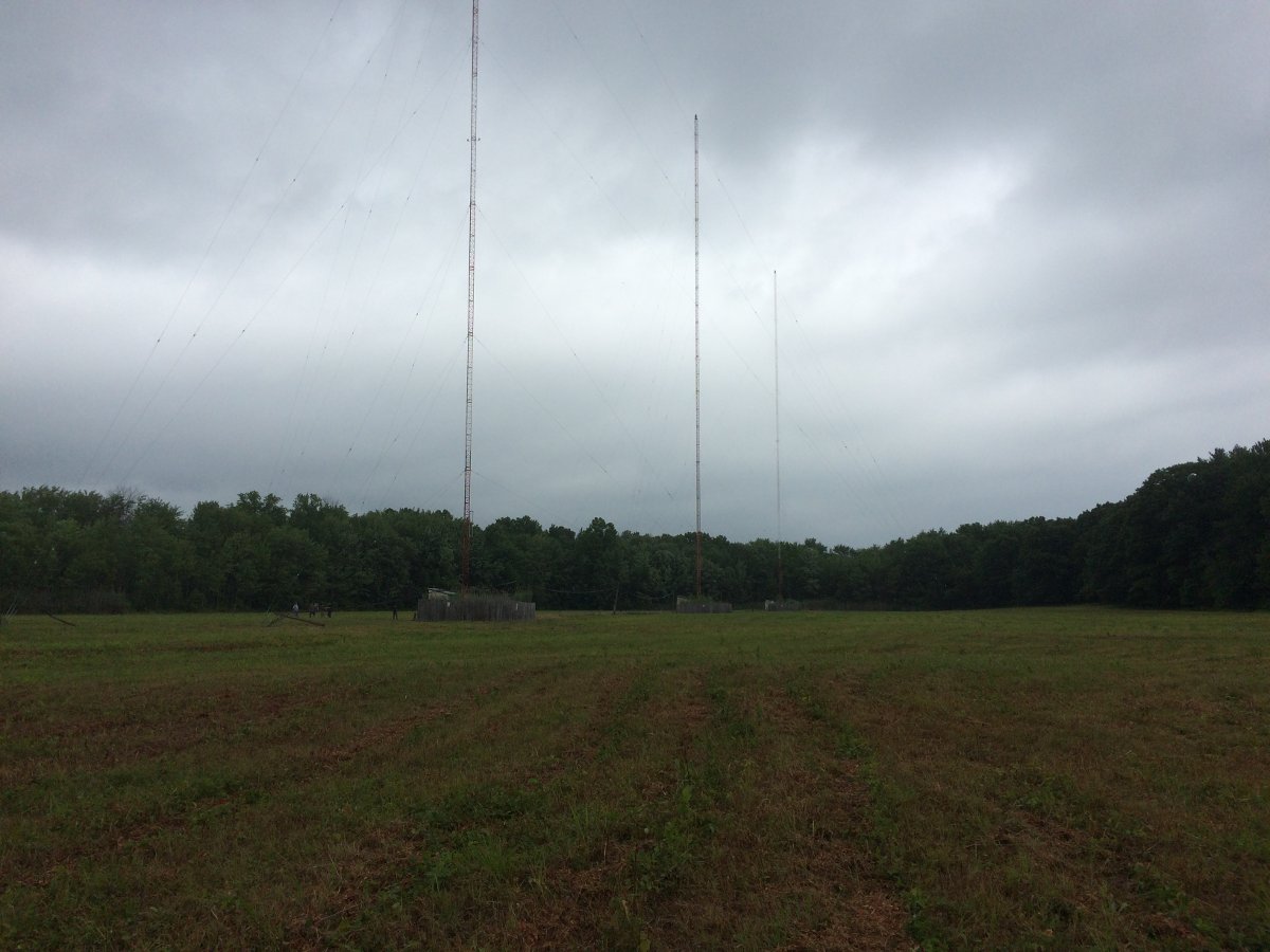
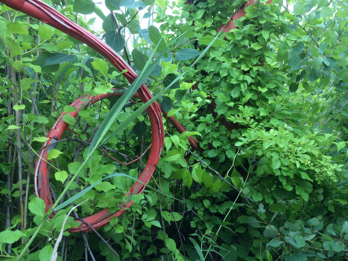
WGHQ in Kingston, NY has been downgraded from a 5KW DA-1 to a 1KW non-DA system. This was done because two of the three towers in the directional antenna array dated from 1960, were in very rough condition and needed to be replaced. The remaining tower (furthest from the transmitter building) had been replaced in 1994, is in good condition, and is being kept as the non-directional radiator.
Here are a few pictures:
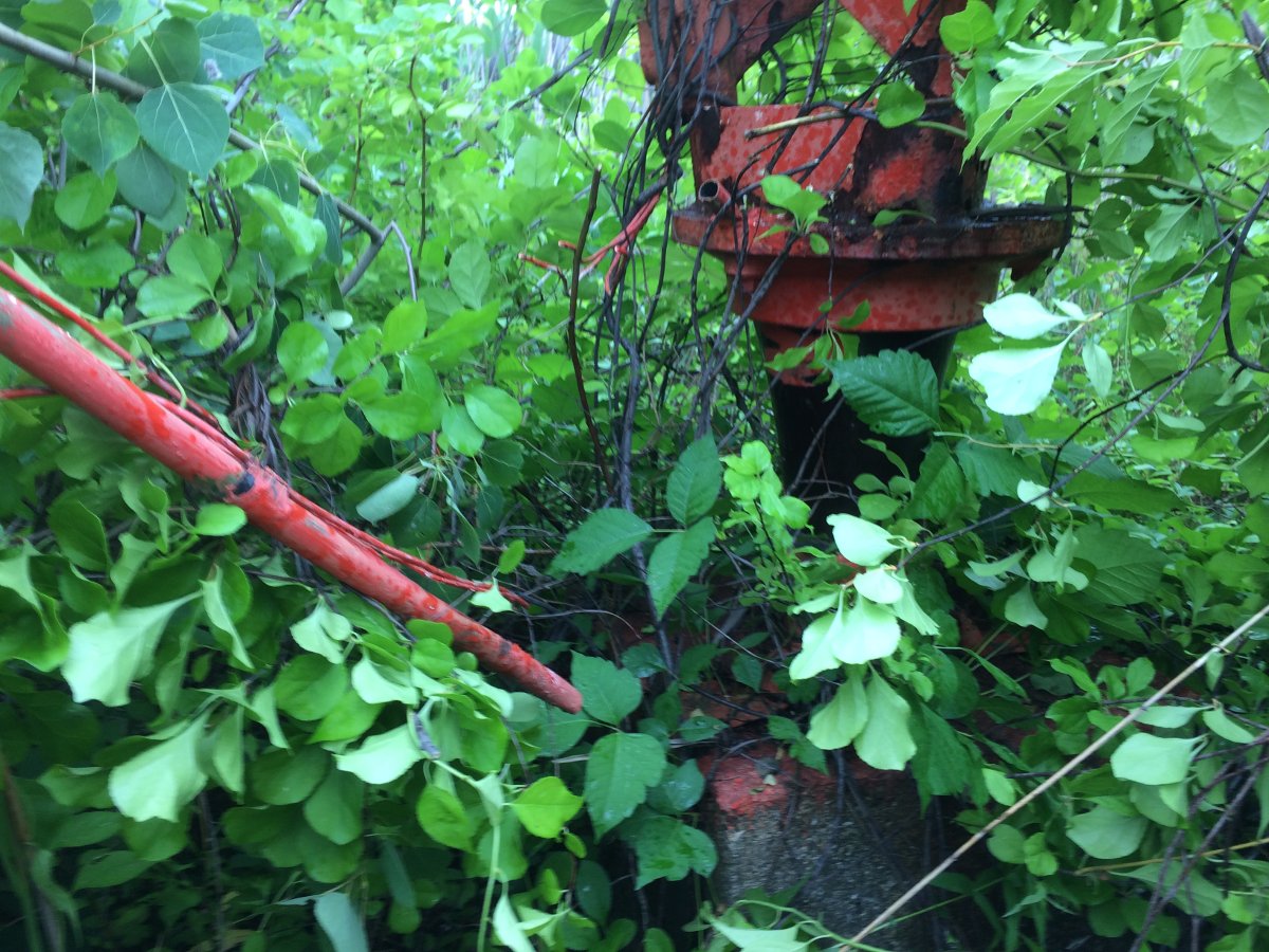
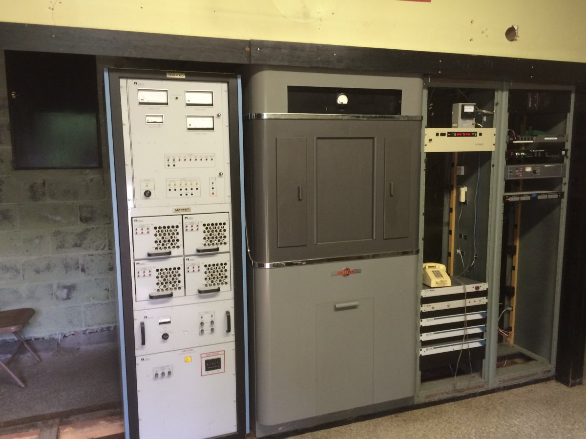
WGHQ 3 tower directional antenna array, Port Ewen, NYMore deferred maintenanceRF and tower light feed disconnected from tower baseSecond tower base vegetation not as bad, tower disconnectedWGHQ transmitter and original Collins phasing cabinet
First tower video (sorry, I appear to have no idea what I am doing with the camera):
Second tower video, this one is better:
Towers on the ground:
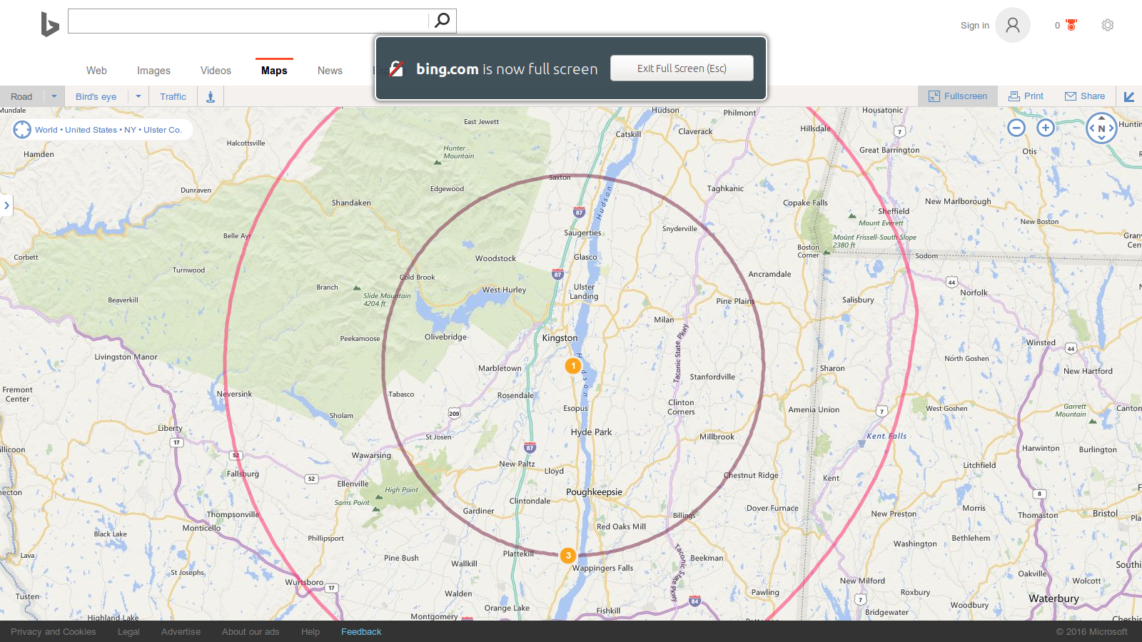
I made measurements on the third tower and constructed a temporary ATU with parts on hand to get the station back on the air. They are now running 1 KW day, 38 watts night, as per their CP. I will be going back up to finish the job once the brush has been removed from around the existing tower and the ATU building has been repaired. The coverage with 1 KW is not bad, actually:
Remember way back when, perhaps in high school or college, you met this really cool person who seemed to be wonderful in every way? Yeah, then you got to know them a little better, and, well, those first impressions changed a little bit.
Crossed Field Antenna, Courtesy of Wikipedia
The Crossed Field Antenna (CFA) sort of reminds me of my first prom date. There was a lot of promise there, but plans fell through.
From a 1999 Radio World article:
Imagine an AM antenna one–fiftieth of a wavelength long, that needs no radial ground system, occupies a small parcel of land, produces little or no RFI (Radio Frequency Interference), has great bandwidth and performs better than a full–sized vertical radiator.
This potential new antenna was all the rage during the early 00s or whatever you call that decade. I remember thinking to myself; I will believe it when I see the test results. At one point, there was a battery of tests run in the installation in Egypt and China. The test results are spotty at best, however, none of these installations performed up to expectations. While it looks like a cool idea, and it would have been great to see it succeed, it seems that sheer willpower alone will not make a particular system work outside of the laws of physics. There are a few of these still in operation out in the wild, mostly in Egypt.
More and more wireless LAN links are being installed between the transmitter and studio. Often these links are used for network extension, remote control, site security, VOIP telephony, and sometimes even as a main STL. These systems come in several flavors:
Moseley LAN link or similar system. Operates on unlicensed 920 MHz (902-928 MHz) band. Advantages: can use existing 900 MHz STL antennas, can work reliably over longer distances, transmitter, and receiver located indoors. Disadvantages: slow, expensive
ADTRAN TRACER or similar system with indoor transceivers and coax-fed antenna systems. Operates on unlicensed or licensed WLAN frequencies. Advantages: fast, transmitter and receiver located indoors, can be configured for Ethernet or T-1/E-1 ports. Disadvantages; expensive
Ubiquiti Nano bridge or similar system where the transceiver is located in the antenna, the system is connected via category 5/6 cable with POE. Operates on unlicensed or licensed WLAN frequencies. Advantages; fast, relatively inexpensive. Disadvantages; equipment located on the tower, difficult to transition base insulator of series fed AM tower.
Ubiquiti Rocket or similar system where the antenna and transceiver are separate, but the transceiver is often located on the tower behind the antenna and fed with category 5/6 cable with POE. Operates on unlicensed and licensed WLAN frequencies.
For the first two categories of WLAN equipment, standard lightning protection measures are usually adequate:
Good common point ground techniques
Ground the coaxial cable shield at the tower base and at the entrance to the building
Appropriate coaxial-type transmission line surge suppressors
Ferrite toroids on ethernet and power connections
For the second two types of WLAN equipment, special attention is needed with the ethernet cable that goes between the tower and POE injector or switch. Shielded, UV-resistant cable is a requirement. On an AM tower, the shielded cable must also be run inside a metal conduit. Due to the skin effect, the metal conduit will keep most of the RF away from the ethernet cable. Crossing a base insulator of a series excited tower presents a special problem.
The best way to get across the base insulator of a series excited tower is to use fiber. This precludes the use of POE which means that AC power will be needed up on the tower to power the radio and fiber converter. This may not be a huge problem if the tower is lit and the incandescent lighting system can be upgraded to LEDs. A small NEMA 4 enclosure can house the fiber converter and POE injector to run the WLAN radio. Some shorter AM towers are no longer lit.
Another possible method would be to fabricate an RF choke out of copper tubing. This is the same idea as a tower lighting choke or a sample system that uses tower-mounted loops. I would not recommend this for power levels over 10 KW or on towers that are over 160 electrical degrees tall. Basically, some 3/8 or 1/2-inch copper tubing can be wound into a coil through which a shielded ethernet cable can be run. Twenty to twenty-five turns, 12 inches in diameter will work for the upper part of the band. For the lower part, the coil diameter should be 24 inches.
In all cases where CAT 5 or 6 cable is used on a tower, it must be shielded and the properly shielded connectors must be used. In addition, whatever is injecting power into the cable, ether POE injector or POE switch must be very well grounded. The connector on the shielded Cat5 or 6 cable must be properly applied to ensure the shield is grounded.
In addition to that, some type of surge suppressor at the base of the tower is also needed. Tramstector makes several products to protect low voltage data circuits.
Transtector APLU 1101 series data line protector
These units are very well made and designed to mount to a tower leg. They come with clamps and ground conductor designed to bolt to a standard copper ground buss bar.
Transtector APLU 1101 series data line protector
There are various models designed to pass POE or even 90 VDC ring voltage.
Transtector APLU 1101 series data line protector
This model is for POE. The circuit seems to consist mostly of TVS diodes clamping the various data conductors.
As more and more of these systems are installed and become a part of critical infrastructure, more thought needs to be given to lightning protection, redundancy and disaster recovery in the event of equipment failure.
Most ordinary field engineers will not need to design an ATU in the course of their normal duties. However, knowing the theory behind it can be very helpful when troubleshooting problems. Also, fewer and fewer people understand RF these days, especially when it comes to AM. Knowing a little bit can be an advantage.
We were working on an AM tower recently when several discrepancies were noted in the ATU:
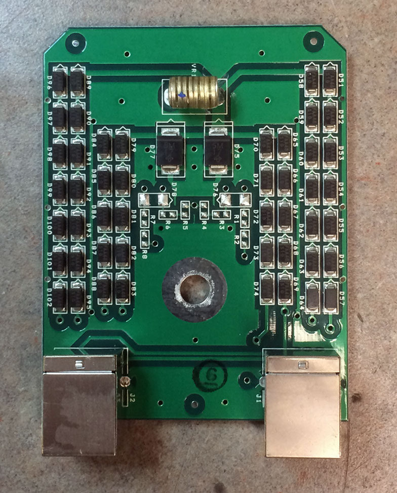
WFAS ATU, 1230 KHz, 1 KW, N-DA
This was connected to a 202° tower. There were several complaints about seasonal shifts and narrow bandwidth. The VSWR meter would deflect slightly on high-frequency audio peaks, always a bad sign. A little bit of backstory is in order. WFAS signed on in 1930 using a four-legged self-supporting tower. This tower was used until about 1986, when it was replaced with a series excited, guyed tower. The ATU in use was initially designed for the replacement tower, which likely had a good bit of capacitive reactance. I am speculating on that, as I cannot find the original paperwork for the replacement tower project. At some point, somebody decided to ground the tower and put a skirt on it, likely to facilitate tower leasing. The skirt was installed, but the ATU was never properly reconfigured for the high inductive reactance from the skirted tower. The truth is, the Collins 820-D2 or Gates BC-1G tube-type transmitters probably didn’t care. They were probably like; bad load, meh, WHATEVER! Although the audio quality likely suffered. That all changed when Broadcast Electronics AM1A was installed. To fix the bad load problem, a BE 1 KW tuning unit was installed next to the transmitter.
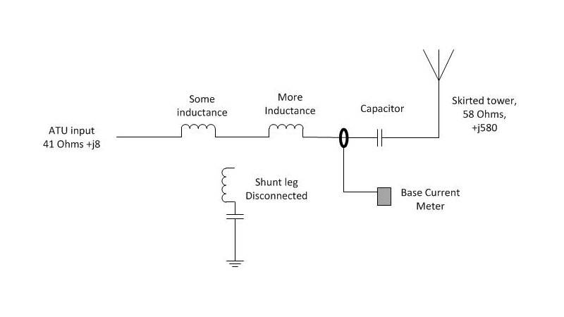
Technically, there are several problems with the above circuit, starting with the capacitor on the wrong side of the base current meter. This capacitor was installed outside of the ATU between the tower and ATU output. Was the base current meter really measuring the base current? I don’t know, maybe? The shunt leg was lifted but both of the inductors of the former T network were left in the circuit.
We reconnected the shunt leg and moved the capacitor inside the ATU and to the correct side of the base current meter. After several hours of tuning and fooling around with it, the ATU is still narrow-banded, although now at least the input is 50Ω j0. I believe the current design has too much series inductance to be effective.
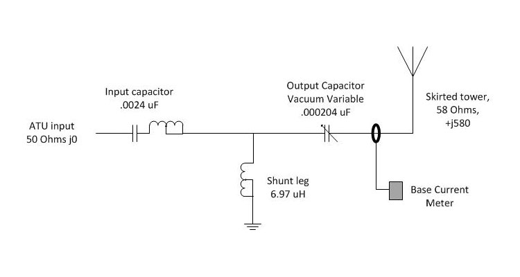
Thus, a redesign is needed. I think, because of the inductive reactance of a skirted tower, a phase advance T network will lead to best bandwidth performance. The basic design for a +90-degree phase advance looks like this:
WFAS +90 phase advance ATU, 1230 KHz, 1 KW, N-DA
To calculate the component values for the ATU, some basic arithmetic is required. The impedance value for each leg in a +/- 90 degree T network can be calculated with the following formula:
Z = √(inputZ × outputZ)
Where Z = impedance per leg Input Z = the ATU input impedance, 50Ω Output Z = the antenna resistance, 58Ω
Thus: Z =√ (50Ω × 58Ω)
Z = 53.85Ω
Formula for Capacitance: C = 1/(2Π × freq × XC)
Thus for the input leg: C = 1/(6.28 × 1.23MHz × 53.85Ω)
C (input) = 0.0024 μF
Formula for Inductance: L = XL/(2Π × freq)
Thus for the shut leg: L = 53.85Ω /(6.28 × 1.23 MHz)
L (shunt) = 6.97 μH
For the output leg, we must also consider the inductive reactance from the tower which needs to be cancelled out with capacitance. Thus, the output capacitor needs to have a value of 53.85Ω + 580Ω = 633.85Ω
Thus for the output leg: C = 1/(6.28 × 1.23MHz × 633.85Ω)
C (output) = 0.000204 μF
The amazing thing is, all of these components are available in the current ATU, they just needed to be rearranged. The exception is the vacuum variable capacitor, which I salvaged from an MW-5 transmitter many years ago. I donated that to the project, as I am tired of looking at it in my basement. The reason for the vacuum variable capacitor will become evident in a moment. The input capacitor will be slightly over value, which will require the inductor to tune out the excess capacitance. A good design rule is to use minimum inductance to adjust the value of a fixed capacitor, thus the capacitor should be not more than 130% of the required value.
About the Vacuum variable output capacitor; in the existing ATU had a 0.0002 μF capacitor already. With a +90° phase shift, this capacitor is likely adequate for the job. The vacuum variable may be pressed into service if something other than a +90° phase shift is needed for optimum bandwidth. That will be the topic of my next post.
Final consideration is the current and voltage ratings of the component. As this is a re-build using existing components, chances are that they already meet the requirements. On a new build or for replacing parts, one must consider the carrier power and modulation as well as any asymmetrical component to the modulation index. For current and voltage each, the value is multiplied by 1.25 and then added to itself. For a 1,000 watt carrier the input voltage on a 50 ohm line will be approximately 525 volts at 10 amps with 125% modulation. A good design calls for a safety factor of two, thus the minimum rating for component in this ATU should be 1050 volts at 20 amps, rounded up to the next standard rating. The capacitor on the output leg should be extra beefy to handle any lightning related surges.
The current rating for a capacitor is usually specified at 1 MHz. To convert to the carrier frequency, the rating needs to be adjusted using the following equation:
IO = IR√ FO
Where: IO: current rating on the operating frequency IR: current rating at 1 MHz (given) FO: operating frequency in MHz
The vacuum variable output capacitor is rated for 15,000 volts, 42 amps. Adjusted for frequency, that changes to 46 amps. The calculated base current is 4.18 amps carrier, 9.41 amps peak modulation. Thus, the capacitor on hand is more than adequate for the application.