Category 7 Cable

As data transfer technology progresses, so do cable types.  Category 6 UTP copper cable is commonly used today in ethernet installations where 1000BaseT (or gigabit ethernet) systems are required. Cat 6 cable has a certified bandwidth of 250 MHz (500 MHz for Cat6a). Category 6 cable is a newer version of Category 5 and 5e cable wherein the wire pairs are bonded together and there is a separator to keep each pair of wires the same distance apart and in the same relationship to each other.  The four twisted pairs in Cat 6 cable is also twisted within the overall cable jacket.

Category 7 cable is much different from its predecessors.  It has an overall shield and individual pairs are shielded:

Category 7, STP ethernet cable

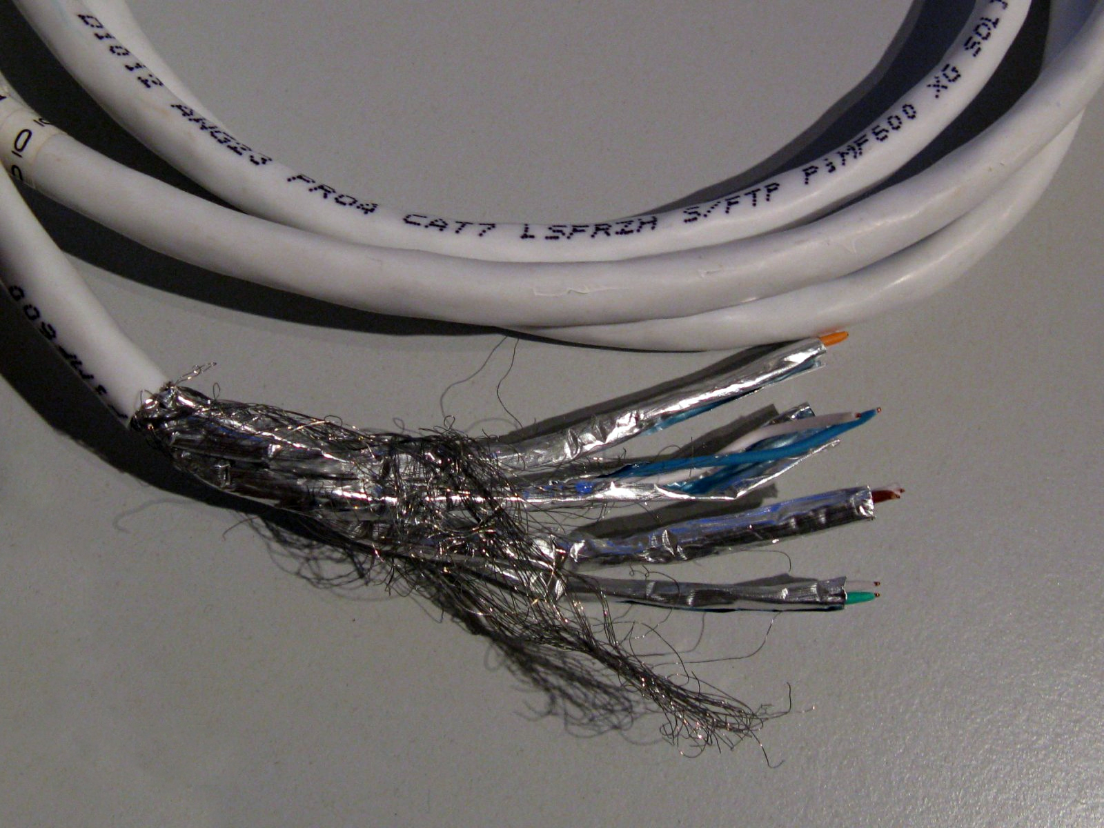
Shields on individual pairs are required to reduce cross-talk (FEXT, NEXT). It also requires special shielded connectors called GG45 plugs and jacks.  Pinouts and color codes are the same as gigabit ethernet (Category 5e and 6) however, Category 7 (ISO 11801 Class F) jacks and plugs also have to contact the corners of the connector or jack.  This allows better shielding.  A small switch in the jack senses when a Category 7 type connector is inserted and switches to the corner contacts, thus keeping jacks and patch panels backward compatible with Category 5/6 cables.

Category 7 GG45 connectors, jack and plug

Category 7 cable is rated for 600 MHz bandwidth (1000 MHz for 7a) which translates to 10 GB ethernet.  This was previously the domain of fiber cable.  Copper cable has some advantages over fiber; lower propagation delays require less complicated equipment, copper is less expensive than fiber and more durable.  It is nice to have the flexibility to use copper cable on 10 GB ethernet for runs of 100 meters or less.  Longer runs still require fiber.

Category 7 and 7a cable looks remarkably similar to the older Belden multipair “computer cable” pressed into service as audio trunk cable seen so often in older studio installations.

Blown up surge suppressor module

This is a picture of a surge module taken from an LEA series type surge suppressor:

LEA MOV module destruction
LEA 600 volt MOV module

Looks like it took a pretty significant power hit, enough to explode several MOVs.  This site is at the end of a long transmission line that stretches across an entire county.  Over the years, the station has made many complaints to the utility company about the quality of their power and the frequency of interruptions encountered at this transmitter site.  Occasionally, something will happen.  Often times it is the figurative shoulder shrug.

That is why we installed the surge suppressor.

Proper drive levels for a Harris SX series transmitters

I was working on a Harris SX5 the other day and snapped a picture of the scope while measuring RF drive levels.  There are still quite a few of these units out in the field, judging from my search engine results.  I thought it would be helpful to post something about it.  The RF power amp boards for the Harris Gates solid-state AM series transmitters are the same design, I believe.

In order to fully drive the RF MOSFETs in this particular series of transmitters (Harris SX1, 2.5, and 5 including A models) at least 26.5 volts peak to peak is required.  Less than that and the device will turn full-on and internally short.  To measure RF drive, the transmitter must be in local with control voltage on, with the rear door interlock defeated (this can be safely done if the transmitter is wired with separate AC feeds for control and RF power supply). Make sure the RF power supply is defeated and will not turn on.  Measure across the input of each of the toroids that feed the gates of the RF devices.

Harris SX series transmitter drive level test
Harris SX series transmitter drive level test, 27.45 volts, 1,110,000 Hz

It should measure between 26.5 and 29.5 volts. This one measures 27.45 volts peak to peak. Each input toroid on every PA board should be measured as the toroids themselves have strange failure modes and may pass resistance and continuity tests, yet still not provide proper drive voltage to the attached devices. This has to do with core permeability.  Each toroid feeds two RF MOSFETs, replace part is IRF-350.

As always when dealing with an SX transmitter, good luck.

We are off the air!

A phone conversation that occurred one Saturday morning:

DJ: (answers hotline) Hello?

Myself:  This is Paul from Radio Engineering Services, you called the answering service and said you are off the air.

DJ: Yes!  The red bat light is flashing and everything!

Myself: Okay, did you try to put the backup transmitter on?

DJ: No.  I didn’t want to mess anything up.

Myself:  You are off the air; I don’t know how things can be more messed up than that

DJ: (laughing) Okay, you’re right.

Myself: Do you have the directions for the backup transmitter?

DJ: Yes, they are right here

Myself: Okay, go ahead and do that, I will call the local engineer and see if I can get him out to the transmitter site, then I will call you back.

DJ: Okay, thanks.

The good news is the backup transmitter came on and they were back on the air.  It is also nice to know that the station has a live DJ on Saturday morning at 7:00 am, many do not.  The main transmitter power outage was likely due to a utility company transient, the area had suffered an ice storm the day before and they were out restoring power that morning.

At least this was a real emergency, I used to get calls at home that the headphone jack on the console was loose.  I took the home phone number down after that.