The lease is up, it’s time to move! Yay, we get to rip apart the old place and redo it! Again! It seems to be a matter of course that every few years a radio station will move. Such is the case with WKZE in Red Hook (the town, not the area in Brooklyn). Their lease is up on the “Grotto” location, so the owner has decided to move to a new location, closer to the center of town.
The new location was the former thrift shop. I know this because while I am working there, a constant stream of older people stop by and tell so. Once, while working alone doing some pre-move work punching down wires and computer network cables, I had to use the facilities. There I sit, on my porcelain throne, when I hear, “Hello?” in an old shakey voice. A quick glance at the door reveals it is not locked. Oh, NOs! Okay, don’t say anything, she’ll go away.
“Hello?”
“Hello?”
“Hello, is anybody here?”
“Hello? Very strange, the doors are open but nobody is here. Hello?”
Oh for the love of Pete, “I’m in the bathroom,” I finally said.
“Where is the bathroom?” said the interloper.
I refused to say anything else and she finally left. She could have taken all my tools if she wanted to.
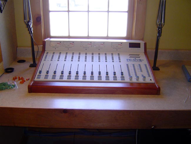
Anyway, the studios themselves are pretty simple, one production studio and one air studio. A T-1 line to the transmitter site, turned out the be the hardest thing about the entire operation. We moved the old Radio System consoles rather than purchasing new equipment. Radio Systems has a program called a Millennium upgrade, where you buy a new control surface, which replaces all moving parts, for something like $2,300.00 or so. For that, basically, a new console is had.
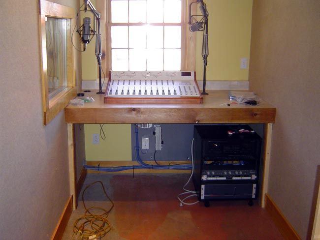
The new production room is long and narrow.
The air studio is large and spacious. They often have live music from this studio, which is really cool. The station uses Prophet Systems automation equipment, although it is live most of the time.
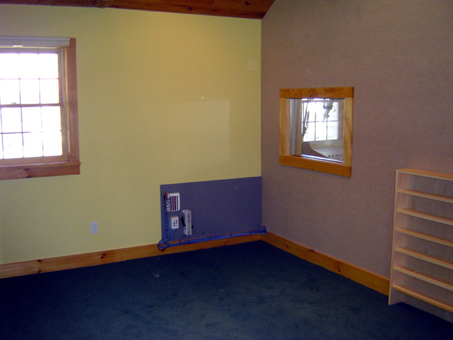
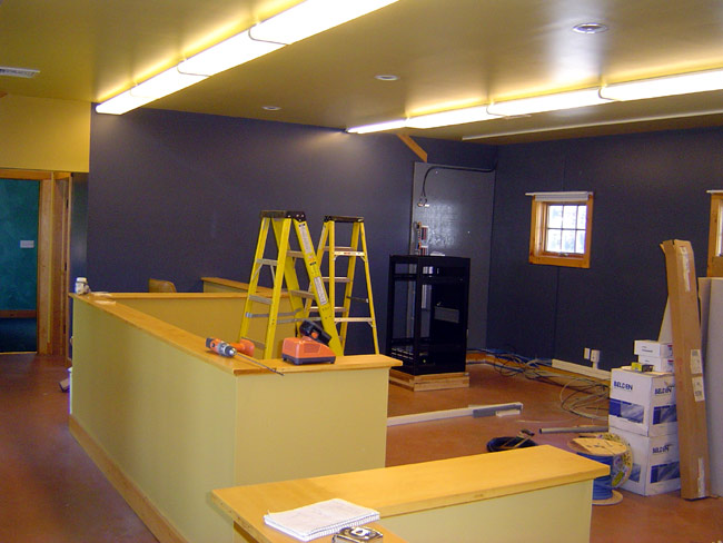
The main office area is one large room where desks will be located.
We are moving in stages:
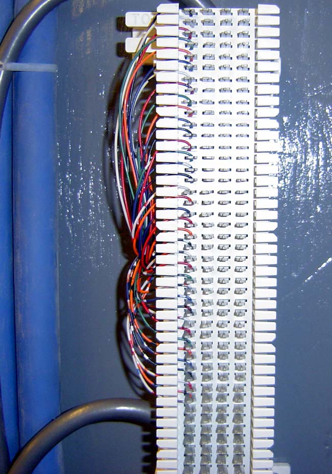
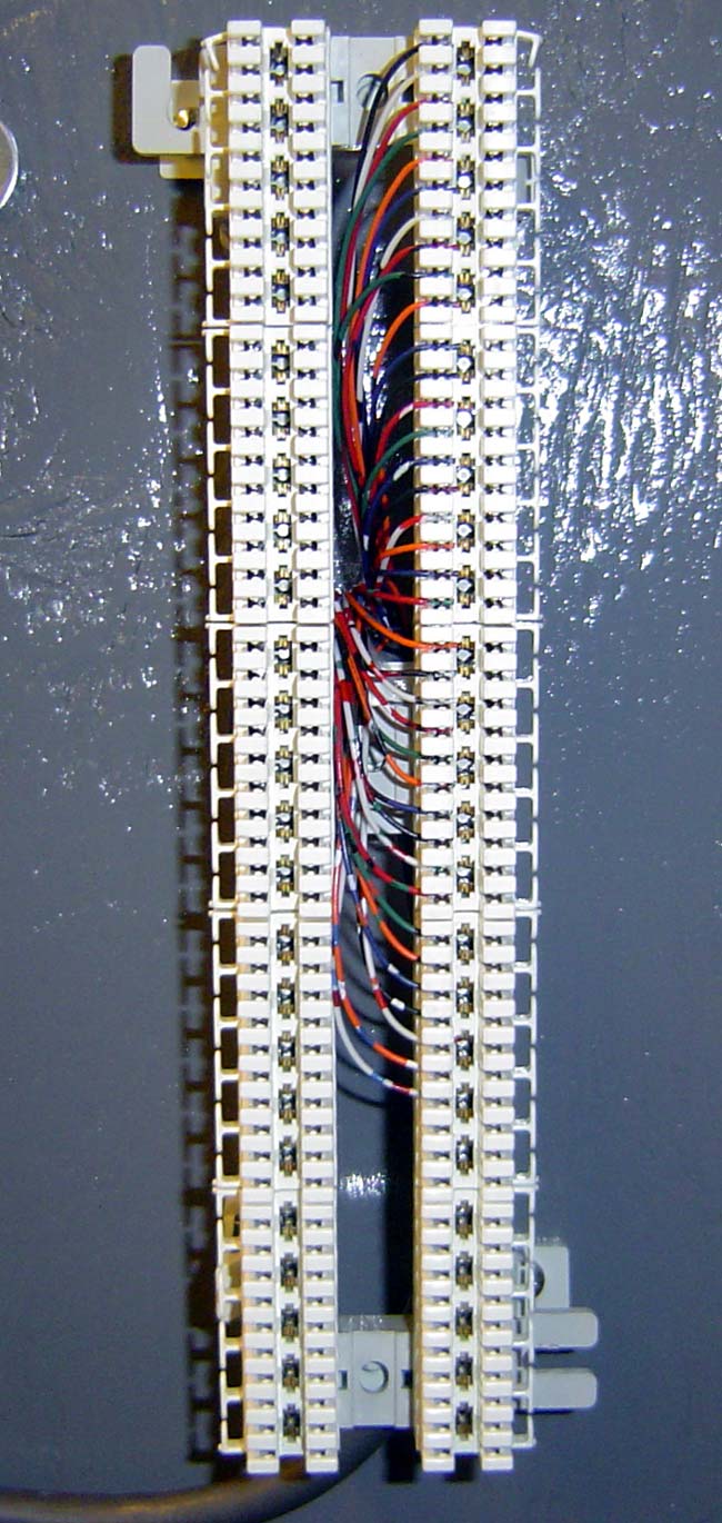
- Prep work, installing all the computer network cable, phone system cable, pulling all the audio and control wiring. Then the contractor finished up the drywalling and painting. Nice Colors!
- Ordering phone lines and T-1 line. Ahhh, the phone company, such a pleasure to deal with, we had to pull a new cable through the underground conduit from the street to the building because the old cable did not have enough pairs. The conduit length is about 75 feet or so.
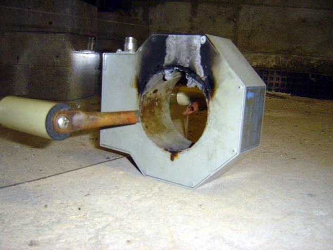
- Removed the old production room console and took it to the shop to rebuild. It was not that difficult really, although a little cumbersome. I throughly cleaned out all the dust dirt and other detreious materials from the console frame and install the new control surface. I also checked all the power supply voltages with an oscilliscope to make sure there was no ripple. The original consoles were made in 1992, not bad for an 18 year old board.
- Built a new production room with the rebuilt board.
- Tested all computer jacks, audio wiring, etc prior to move.
- Move T-1 circuit and all office and studio telco lines to the new location. Fortunately, the phone company is a local company not the big V we have in other cities. They were able to work with us and get things paralleled to the new location, something a large company might not have understood.
- On the air from the production room at the new location
- Remove the main rack, intact and move it to new location
- Remove office phone system and install at new location
- Remove and rebuild old air studio console
- Install rebuilt air studio console in new studio, wire
- Transfer operation to new studio
Right now, we are on step #6. That is going to be done next Tuesday (the day after memorial day) morning I believe. We should have the move completed by the end of the week. I’ll post updates as they become available.