Delta Current Sample Toroid

Another example from my blown-up shit collection, artifacts division:
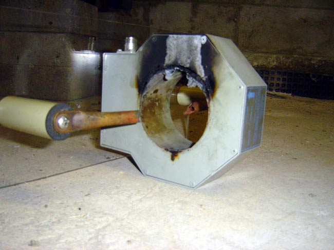
Delta TCT-1HV current sample toroid destroyed by lightning

This is a Delta TCT-1HV current sample toroid that was pretty well destroyed during a thunderstorm.  I mounted it on a piece of plexiglass because I think it looks cool.  This unit was installed at the base of the WGY transmitting tower.  One June evening, I received a call from the station operator (back when they had live operators) that the air signal sounded kind of “funny.”  So I turned on the radio and sure enough, if one thinks a radio station that sounds like a motorboat is funny, then, why yes indeed, it did sound funny.

Since I only lived a few miles away from the site, I jumped in the trusty truck and headed over.  Upon arrival, I found the MW50B on the air at full power, with the carrier power swinging wildly from 20-90 KW with modulation.  Hmmmm, bad power supply?  Turned the transmitter off and tried to place the backup transmitter on the air.  Now the old Gates BC5P had never been super reliable in the first place, but it was odd that it would not even run at all.

Then I had a hunch, let’s walk out to the tower I said to my assistant who had shown up to help.  When we got to the ATU building it was filled with blue smoke.  Ah ha!  Somebody let the magic smoke out of one of the components!  I was expecting a capacitor blown in half but was surprised to find the copper tubing that connected the ATU to the tower melted in half.  Lightning must have caused an arc between the tubing and the toroid and for some reason, the transmitter kept on running while it was arcing.  The copper tubing in the picture with the toroid is only missing about six inches, the way the system was mounted at the tower base, fourteen inches of copper tubing was missing, or rather melted into a puddle on the bottom of the ATU.

I quickly found another piece of 1/2-inch copper, cut it to length, flattened out the ends with a hammer, and drilled mounting holes.   Luckily I was able to get everything back in order quickly and the station returned to the air about an hour or so after it went off.

Everything has a cause.  Investigation showed that the VSWR circuit on the MW50 had been disconnected from the directional coupler.  The lead was un-soldered and taped off, so it was quite intentional.  I spoke briefly with two of the three prior engineers that had serviced the MW50 over the years, they both blamed the other one.  I surmise this; The WGY tower was prone to lightning strikes because of its height.  Even if the tower was not directly struck by lightning, oftentimes the guy wires would arc across the insulators, causing the MW50 to momentarily interrupt the PDM signal and drop the carrier for about a second.  Some programming people at the station did not like this, it sounded bad on the air, so one of those guys undid the VSWR circuit, and voila! No more momentary outages during a thunderstorm! Brilliant!  Except for the 60-90 minute outage one night…

Sometimes it is better to tell the program directors that their idea is not good, then move on.
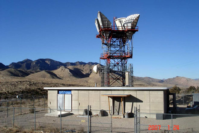
Somewhere in Utah, a phone company is missing it’s microwave site…

I followed this link to this site called “SurvivalRealty.com” and saw this article about what looks to be a former ATT microwave relay site in Utah turned into a residence.  The site is much smaller than the former ATT site in Kingston that I profiled in this post.   Still, that is a Western Electric tower and those are KS-15676 antennas.

Former ATT microwave site turned into a residence

If I were that guy, I’d take those antennas down a scrap them.  Looks like the waveguides are already gone.  I might have tried to put some windows in while I was renovating it.  It would drive me crazy to live in a house without any windows.  I guess if one were waiting for the big one, windows might not be a desired feature of a survival bunker.

I wouldn’t really call it a “communications bunker” though.  I’ve been in communications bunkers, they are mostly underground and are much more robust than that building.  Still, it is built better than an ordinary commercial building or a regular house.   It would take a special person to live out in the middle of nowhere like that.

Broadbanded AM antennas

Partly for my own edification, partly just because, here is some information about AM antenna systems and their bandwidth. An AM tower is a radiator that, simply by the physical constraints of the tower structure itself, is pretty narrow-banded, even under the best conditions. Add to that, antenna tuning units, transmission line phasing, antenna phasing units, diplexing units, and things can get very squished outside of the immediate carrier frequency. This seems to be a particular problem with directional antennas, which most AM stations employ.

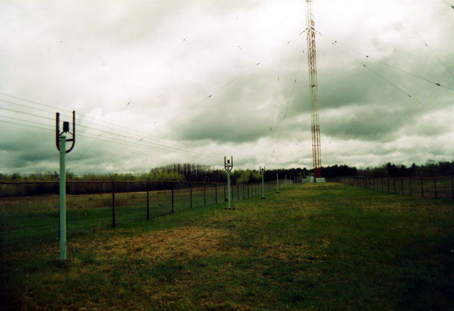
WGY 810 kHz, Schenectady, NY transmitting tower w/open feed line
WGY 810 kHz, Schenectady, NY transmitting tower with open transmission line

As an engineer, you can get some idea of how narrow an antenna system’s bandwidth is by looking at the base impedance measurement.  Every AM station is required to keep the latest impedance measurement on file.  When looking at these measurements, there will be one curve that indicates base resistance (R) and another curve that indicates reactance ( X, although often noted as + or -j).  If the resistance and or reactance curve is slopped steeply at the carrier frequency and out to 20-30 kHz, it is a narrow tower.  Add to that the different phase shifts of an ATU and or Phasor and things will be compounded.  That is why it takes a professional to design and tune up these things, a poor design will never sound right.

Another way to get some idea of bandwidth requires a field strength meter.  Modulate the transmitter with a 10 kHz tone at 50% modulation.  Then, away from the near field, measure the carrier and 10 kHz +/- the carrier frequency on the log scale.  The sidebands should be symmetrical and about 1/4 the carrier level.

Generally speaking, antenna systems need to be designed for low VSWR across the entire side band range (+/- 10 kHz from the carrier) as well as symmetrical distribution of radiated energy across the lower and upper sidebands.  Several factors influence these conditions:

  1. Electrical tower height is perhaps the hardest thing to change once a tower is constructed.  Short towers (less than 80 electrical degrees), or very tall towers, (taller than 200 electrical degrees) present problems.  If one were constructing an AM station and could choose any tower height, something between 120 to 190 electrical degrees would be ideal.  Existing towers can be top-loaded to add electrical height for an additional 30 degrees or so.  Beyond 30 degrees it becomes difficult to physically attain and therefore impractical in most situations.  Top loading and bottom loading of a tower can reduce bandwidth if done improperly.   Bottom loading an AM tower is almost never done due to the very high voltage and current as the electrical length approaches 180°.
  2. Antenna matching networks can greatly improve or degrade bandwidth, depending on how they are designed.  A T-matching network has more parts and is more expensive, however, it allows for optimum control over the R and jX phasing.  This becomes much more difficult with directional antenna where phase considerations are a part of the station’s antenna field pattern development.
  3. Phasors present the biggest challenge, particularly in the power divider sections.  A tank circuit power divider is the worst choice, and a shunt circuit power divider is the best bandwidth choice, however, it is the hardest to conceptualize.

Obviously, the more complicated the antenna system, the harder it will be to keep the bandwidth open over 20 kHz of spectrum.  This is especially true on lower-frequency AM signals, where the bandwidth is a much larger percentage of the frequency.   Multiple patterns, multiple tower DAs are a nightmare.  Single-tower non-directional stations are the easiest to modify.

As far as the circuit itself, higher Q circuits have smaller bandwidths.  Simply stated, in an alternating current circuit, Q=X/R.  The better the reduction of X, which also has a lot to do with the relationship of the current and voltage phasing, the better the Q will be.  This is why a T network is the best design for an ATU.  With a 90° or 180° tower, this is relatively straightforward.  In towers that are shorter or taller than that, it becomes more difficult as the value of R becomes less friendly.

In most cases, some sort of L/C network can be deployed to decrease the Q of an antenna system at the base of the tower.  Directional stations also need to have the phasing equipment looked at, because, as noted above, certain designs can create bandwidth bottlenecks.  All in all, it is usually an expensive proposition for a multi-tower directional station to broadband its antenna system.  This is another reason why IBOC on AM is destined to fail, many AM towers cannot pass the extended sidebands adequately.

Arbitron PPM; engineering speak

We have a few stations that are currently encoded with the Arbitron PPM encoders.  I did a little research on the encoding method since it is not immediately apparent how they are transmitting their data.

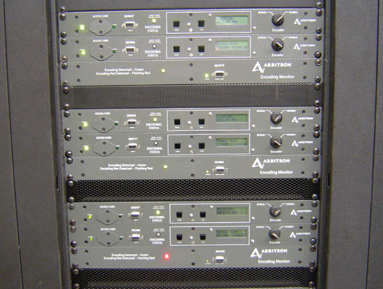
Arbitron PPM encoders

According to Wikipedia, which can sometimes be relied upon, Arbitron used Martin Marietta to help develop the technology.  Martin Marietta (now Lockheed Martin) is mostly known as a defense contractor, they have helped develop several complex military communications systems over the years.

There are no fewer than 39 US patents that cover the technology used in the PPM.  The most significant of these appears to be 7,316,025 which describes the psychoacoustic masking technique employed.

It really is pretty slick, using a sample rate of 8.192 kHz, it transmits 4 bits per second in the 300-3000 Hz range by hitting specific frequencies in that range at varying intervals, adapting to the audio levels to keep the encoding below the programming content.  4 BPS is very slow and thus very robust.  After all, I believe the only formation transmitted is a six-digit encoder serial number.   I did not read all 39 patents to see if anything else was changed in the encoding method, so it may be slightly different.

This type of system would have fairly low overhead, not adding to the station’s bandwidth which is a consideration for FM stations, and in the correct frequency range for most AM receivers on the market today.  Some people have said they have heard the encoding on one of our stations, most notably during silence or very quiet programming.  Perhaps, especially in a dead air situation, one might hear in nearly imperceptible low frequency slow fluttering sound.

If anything, the encoding is perhaps too robust.

Now for the deployment of the monitor technology, which has so many up in arms.  As with other Arbitron ratings methods, the main bone of contention seems to be the size and distribution of the sampling hardware.  Minority groups feel they are underrepresented because the PPM is unevenly distributed.

Rating samples always seem to skew one way or another.  The data samples themselves seem to be too small to accurately predict a station’s listenership.  One anomaly and the entire month or quarter can be thrown off.  The PPM seems to correct some if the issues with keeping an accurately written diary.  One problem with the PPM however, it can also pick up incidental background noise and count it as time spent listening (TSL).

Think of the cubical environment where somebody several cubes away might be listening to a radio station.  To the PPM wearer, it is unintelligible background noise, however, because of the perceptual encoding, the PPM picks it up and it counts as several hours of TSL.

A broader sample would dilute this with other more accurate representations of radio listening.  A broader sample would also alleviate some of the complaints from the Minority Media and Telecommunications Council (MMTC).  First-year physics students would recognize that not enough sample data can make results wildly inaccurate.  Or, as one emergency room doctor stated while washing my knee out with a liter of sterile water after a dirt bike accident, the solution to pollution is dilution.