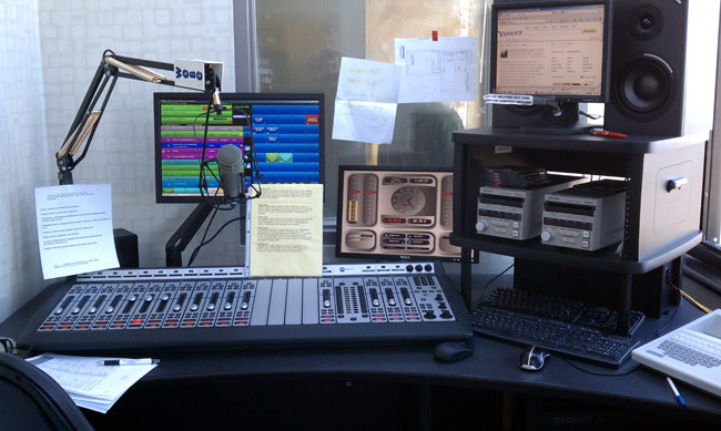
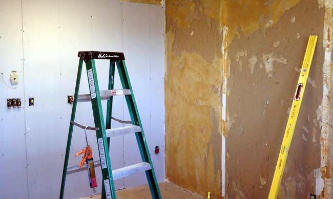
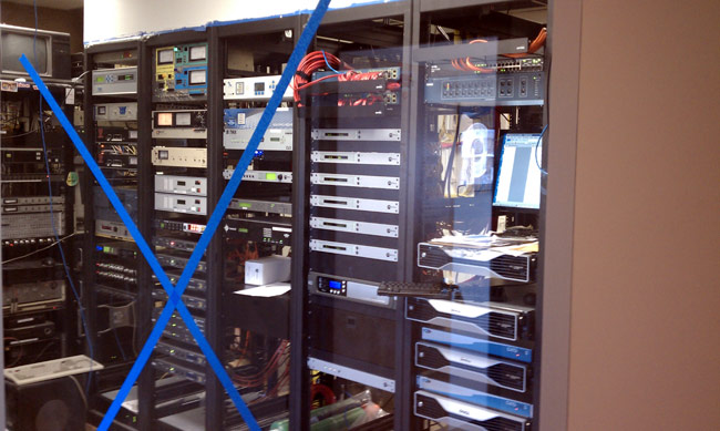
I received a great email from Michael “Catfish” Dosch, console designer for Telos / Axia Audio Systems. The email was sent in response to a comment I posted on the WEBE WICC Studio Build Out post. I thought the email was very interesting and informative, presenting a perspective that most broadcast engineers do not often see or appreciate. I asked Mike if I could use it as the basis for a blog post and he agreed. I am not going to blockquote the entire thing, but here are the unedited email and pictures.
Quote:
“Ken said you had a concern about the ruggedness of our consoles as compared to the old PR&E boards. You might not know this, but I was with PR&E before joining Telos. In fact, I designed many of those old PR&E boards. I guess that makes me an old console designer. Ahem.
The Element design is more modern in construction and styling, but it is no less rugged than those old PR&E boards. In fact, you could stand on it if you wish. The top is a 1/4-inch machined aluminum plate supported by structural aluminum ribs on the backside. The chassis itself is made of custom extruded aluminum structural pieces and machined aluminum side panels. The flat sheet metal on the bottom is not structural, it’s only a cosmetic cover. You’ll see a lot of folded sheet metal in other consoles because it’s cheap and easy. But it’s not as rugged as the Element approach which is why we chose to go with a more complex and expensive mechanical design.
One very visible difference between Element and PR&E consoles is the use of Lexan on the front panels (PR&E would use aluminum or steel on the top panel). This might seem less rugged, but it is actually chosen because it is a more durable surface than painted and silkscreened metal. It is more scratch resistant and it is rear-printed so that the markings never wear out. Silkscreens would wear off under heavy use — particularly next to faders and monitor controls — and look horrible over time. These Lexan panels will look just as good after 15 years as they do now.
But Lexan for all of its durability has its own limitations. The edges can crack under abuse. This is why you see many older Wheatstone consoles (they have used Lexan overlays for many years) with cracks and tears at the very edges of the plastic. This is particularly troublesome in the fader slot. A frayed edge on a faders slot can cut your fingers. That is mighty unpleasant! So when we decided to use Lexan, we wanted to have all the benefits and none of the drawbacks.
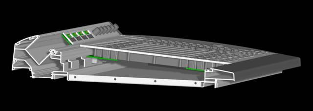
So we designed a machined recess on each channel that allows the Lexan insert to have its outside edges protected by the aluminum. More obvious are the bezels around each button and even the fader slot. Look carefully and you will notice that all of the control bezel edges are above the lexan. The edges of the lexan are not exposed and therefore not prone to cracking, chipping, or splintering.
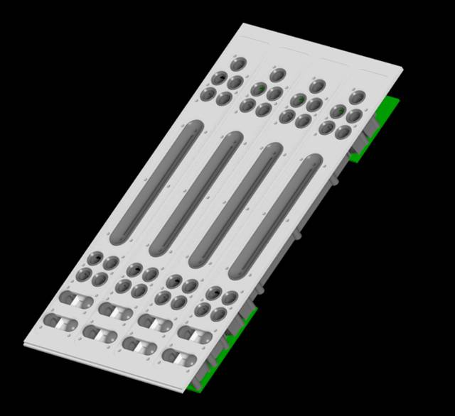
In this drawing, you can see the panel without the lexan. The machined pocket to protect the outer edges of the Lexan, plus the raised edges of the button and fader bezels to protect the edges around the holes. These button guards are also designed to prevent accidental actuation of the buttons. And while the guards are designed to protect accidental actuation, they never hinder deliberate activation. Notice the guards at the sides of the ON/OFF buttons and not on the top and bottom. Even operators with long fingernails will have no problems with these controls. The small round keys are engaged with a light touch of the fleshy pad of the fingertip.
Yes, I think we built great consoles at PR&E. But Axia was a fresh start, a chance to raise the bar even higher, by retaining many of PR&E’s better attributes and improving upon some of the weaker areas. DIPswitch configuration has been replaced with the convenience of the web browser. Spill-prone motherboards and electronics have been eliminated from the control surface. Unreliable monitor pots have been replaced with optical rotary encoders rated for 5,000,000 rotations.
And you asked about the faders. This is a particularly important component in a broadcast console. PR&E used Penny & Giles faders for many years. We used their Series-4000 faders in the X-Class consoles (BMXIII, AMX, ABX and STX). This was their top-of-the-line fader at the time and performed beautifully… for a year or two. Then our clients started experiencing field failures at a very high rate. We worked with P&G on a return/rework/replace program that took years to clean up. Our clients were disappointed and we spent a fortune making things right. It was that experience that caused us to begin searching for alternatives.
The market for high-end faders is quite small. There are tons of consoles out there for live sound, home recording, etc., but these products are sensitive to costs and generally use very cheap faders. There just aren’t enough high-end recording consoles or broadcast consoles being built to attract a lot of fader vendors. After a lengthy search, I disqualified all but two fader companies: P&G and a Japanese firm by the name of Tokyo Ko-on Denpa (TKD). I assigned one of our engineers to create a set of environmental and life-cycle tests to see if the TKD faders could keep up with the P&G faders. We were all shocked by the results.
Out of 100 of each type tested in various environmental conditions and physically cycled for the accelerated equivalent of 10 years of heavy use, we had only one TKD fader failure, compared to more than half of the P&G Series 4000 faders! We defined “failure” as any deterioration to specifications or any discontinuities. All the failed units had discontinuities (audio dropouts). We were able to clean the failed TKD fader and it passed the retest. About half of the failed P&G units were cleaned and passed the retest. So in the end, the practical results were TKD 100% good and P&G 75% good. Not what I expected at all.
We then designed a TKD fader into the Radiomixer. We watched the customer support logs carefully for problems. Out of the first 1,000 console channels shipped, we saw one TKD fader failure during the first year. Warranty replacement of course. The failure rate did not increase with use as you would normally expect. We were seeing consoles with 3 or 4 or 5 years of heavy use with no fader problems at all. I have heard of 20 year old Radiomixers with original faders still working great.
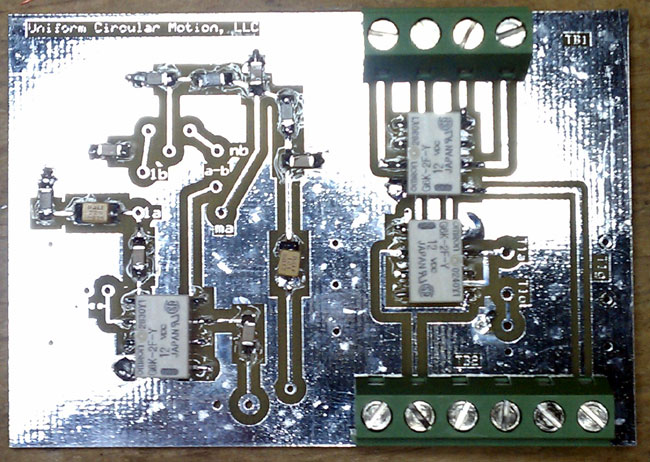
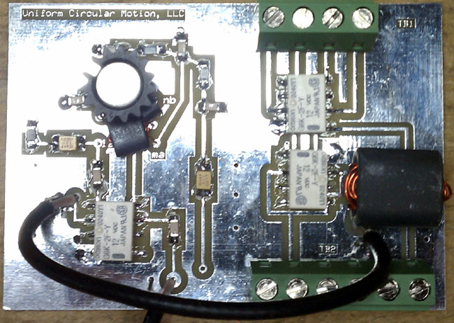
One particularly elegant feature of the TKD fader used in Element is a side loaded wiper arm. This prevents liquids or other foreign matter from spilling into the fader slot and directly into the fader element. This feature alone is probably responsible for extending the useful life of the faders by a considerable amount. Of course, these can be disassembled and cleaned just like a professional fader from P&G, they just don’t need it so often.
Some have the misconception that if a fader is not P&G, it must be cheap. Actually, these are very expensive faders, about the same cost as P&G. But they are so well made, I think they’re worth every dollar. I know there are still some folks out there who remember P&G’s glory days when they made bullet-proof faders. I remember fondly those days as well. But in my experience, the TKD fader is superior to the equivalent P&G fader. We feel so confident, that we warrant all Axia consoles for 5 years, including all components….”
End Quote
That is a great explanation of what goes into one of these consoles right from the designer. The pictures are courtesy of Axia Audio / Telos Corporation and special thanks to Mike for taking time out to give us a glimpse into the mind of a console manufacturer.