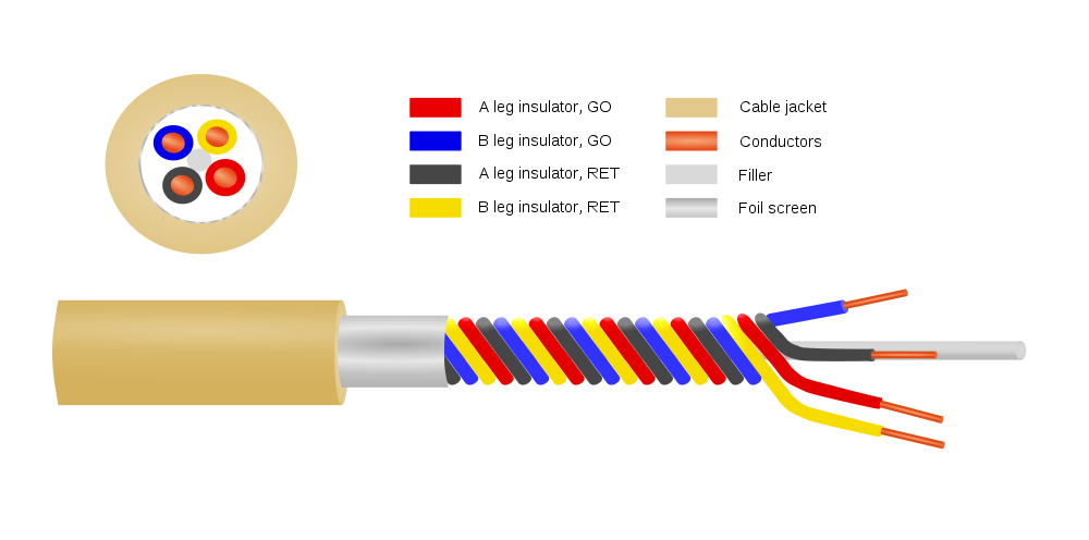
Or Star Quad Microphone Cable, depending on who is making it.
Star Quad Microphone Cable Diagram
This has been around for quite a while, but many studio/broadcast engineers don’t understand it or don’t use it for some reason. Microphones and mic pickups produce relatively low signals when compared to line-level audio. Most microphone preamps have a gain of +50 dB, which means any noise gets amplified and even small things can become major problems quickly.
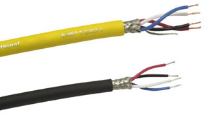
Gepco MP1201 Quadstar Microphone Cable
Under general conditions, most balanced shield twisted pair (STP) audio cable such as the standard Belden 8450 is adequate for stationary microphone cable for short runs. When the cable is not permanently fixed in place, as in hand-held microphones, microphones mounted on booms, or other nonfixed microphone applications, then a flexible cable must be used. Star Quad cable has better noise specifications than standard flexible microphone cable.
The advantage of Star Quad cable for low-impedance microphones (150 ohms) is that the parallel twisted pairs significantly reduce inductive reactance. In AC circuits, inductive reactance acts as a low pass filter, gradually rolling off as the frequency is increased. This effect is cumulative, the longer the cable run, the more inductive reactance is added to the circuit. The result is microphone audio can have smeared or ill defined high frequency audio.
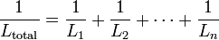
parallel inductance formula
Using two parallel twisted pairs is similar to parallel resistors when it dealing with inductive reactance, it halves the value.
In addition to reducing inductive reactance, the tighter twist found in Star Quad cables reduces the CMRR by about 20 dB. The Star-Quad configuration keeps the conductors in the same relative position to each other as the cable is flexed and moved around. All of this makes it superior to standard STP microphone cable.
Several companies manufacture Quad Star cables:
Belden: 1192A
Canare: L-4E6S
Gepco: MP1201
Mogami W2534
Cardas 4X24
The price of Star Quad cables runs about 40-60 cents per foot (more for the Belden, much more for Cardas) if purchased in bulk. That is about the same range for two conductor mic cables.
As good as this cable is, I don’t think they had this in mind when they made it:
I wonder what the centripetal force on that cable is when the microphone is in full motion. Also, I’d bet that SM58 was none the worse for were after it’s crowd surfing moment.
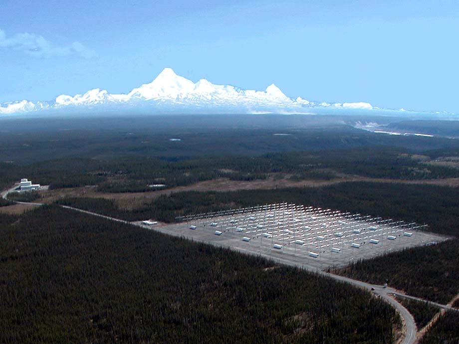
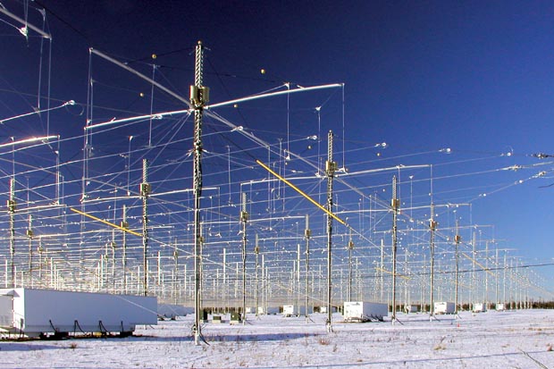
This looks interesting and many people have speculated as to what it does. The High Frequency Active Auroral Research Program, AKA HAARP in the parlance of the acronym heavy US military, is designed to do Ionospheric research.
HAARP antenna array, Gakona, AK. Courtesy HAARP
That array is described as 180 crossed dipoles in a rectangular planar array. The transmitter power output is reported as 3.6 MW with an ERP of 5.1 GW in the frequency range of 2.6-10 MHz. That’s a whole bunch of watts. The array was built around 2004 and operates intermittently at various powers and frequencies.
HAARP array close up, Gakona, AK. Courtesy of HAARP
A view of the individual antennas. They look like broadbanded fan dipoles arranged in cross configuration. Depending on how they are phased, the gain of this system would be a factor of 10 or slightly more.
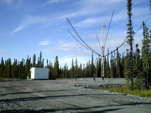
HAARP receiving antenna, Gakona, AK. Courtesy of HAARP
The main focus of this system is to study the Ionosphere, which is a critical part of wireless communications. In the HF frequency range, (and to some extent MF) signals bounce off of the Ionosphere (so called “skip”) and can travel many thousands of miles on relatively low transmitter powers. All satellite based communications pass through the Ionosphere on the way to and back from the satellite, as does GPS. Back in 1990, when the US Navy and Air Force proposed the project, HF radio was a key part of their communications network. Since then, mostly satellite modes have taken over that role, but HF is still relied on heavily. Further, studying the cause and effects of such things as Aurora Borealis, the Van Allen belt, high altitude nuclear burst,VLF, ULF, and other communications phenomena is important not just to the military, but society as a whole. We rely heavily on the communications infrastructure for things like cellphones, broadband internet, telephone service, banking, credit card transactions, etc. It has been long known that disruptions in the ionosphere can impact all of those services.
The problem with the Ionosphere is its location right on the edge of space. Too high for aircraft or weather balloons to reach, too low for satellites, it remains, for the most part, a mystery. The program was founded to research this area by beaming focused energy to small areas and observing the results from a number of different locations.
Of course, the system is not without controversy. It is a big scary looking antenna system in the middle of the woods in the far north. Conspiracy theorists have accused the US of using HAARP as a weather modification scheme. Since it’s construction it has been blamed for:
droughts
floods
hurricanes
thunderstorms
earthquakes
major power outages
TWA flight 800
Gulf war syndrome
Chronic fatigue syndrome
Movement of the magnetic poles
And others. Naturally, none of these things ever happened before the array was constructed in 2004. In another wrinkle, TWA-800 crashed in 1996 off of Long Island, NY. In all fairness to the Conspiracy Theorist, USTPO number 4,686,605 (Eastlund/ATPI) does indeed mention weather modification as a theoretical possibility. While 5.1 GW may seem like a lot of power, I doubt very much that it could compete with the Sun’s output and change weather patterns in any perceptible way.
Everything about this program is top secret, or rather T O P S E C R E T or above. Exactly how it accomplishes these things, no one can say. As with any T O P S E C R E T government program, ample access and pictures are available to the public from a variety of sources and annual open houses that are held.
People generally fear what they don’t understand.
In this respect, the government, through perhaps the sometimes security conscious military, has done itself no favors.
The reality is this: Taking into account free space loss, the distance (100 to 350 KM or 62 to 218 miles) and power levels reportedly being used, the power density is no more than 3 μW/cm2, as given by the HAARP website. My own calculations show: If the ERP is 97.1 dBW or 127.1 dBm, then the free space loss at 100 KM and 2.6 MHz is 80.7 dB, which would be the worst-case scenario and might not be technically possible with those antennas (it would be much larger due to antenna inefficiencies at 2.6 MHz). However, with that configuration, the power density is 0.47 μW/cm2, far below the stated 3 μW/cm2. To put this into proportion, the Sun averages about 7.32 W/cm2 over the entire surface of the Earth. More near the equator, less near the poles. To compare the two; HAARP=3μW/cm2, the Sun=7,320,000μW/cm2. That is not good enough for some because HAARP is located far north, about 62° N latitude, so it gets less sun. Even so, the power from the Sun at 62° N is still many orders of magnitude greater than the HAARP array.
There are plenty of things to be concerned about in this world, this is very low on the list. The conspiracy theorists should do a little more in depth research on their subject matter, it would lend a bit of credibility to their story.
Amplitude Modulation (AKA AM) was the first modulation type to impress audio on an RF carrier. Prior to this, information was transmitted via on/off keying of a continuous wave transmitter using Morse code or some equivalent.
There are several methods for generating AM in a transmitter.
1. Low-level modulation. The modulation is developed in the first stage RF section, then amplified by subsequent stages to full power. Simple and easy to implement, especially for mobile transmitters and SSB installations. Disadvantages come from the need for linear amplification through all the stages requiring class A or AB amplifiers and do not reproduce wide band AM well.
Grid Modulated AM transmitter
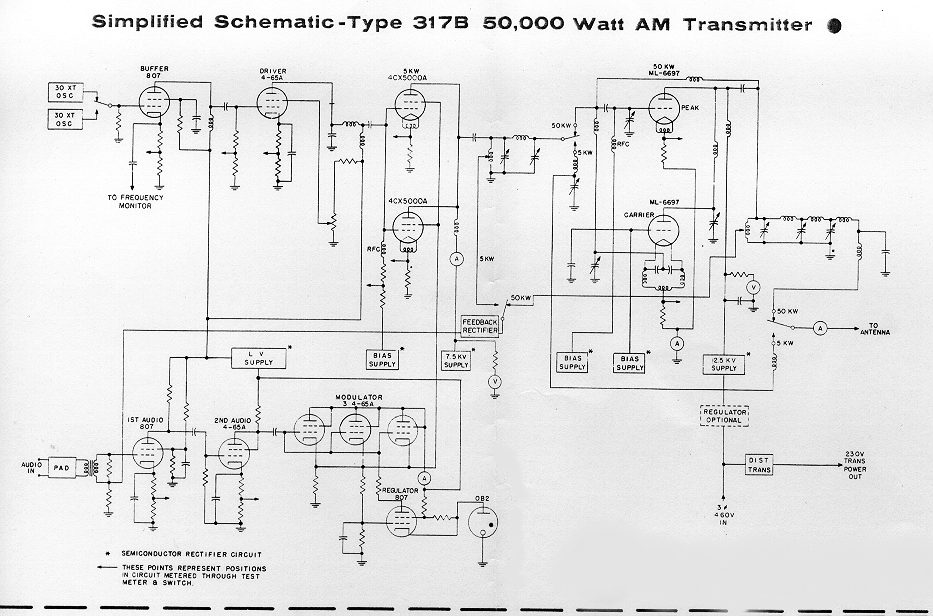
2. Doherty modulation. William Doherty came up with an ingenious way to use a low-level linear modulator with good to excellent efficiency. Under full carrier, no modulation conditions, the carrier tube is generating the RF carrier, and the peak tube is mostly cut off (very little current). When modulation is applied, the peak tube then begins to conduct, the output of this tube is combined with the output of the carrier tube through a 90° LC network, which is the same as a 1/4 wavelength transmission line. The effect of this is to lower the output impedance, thus allowing the carrier tube to modulate 100 percent.
Later, Continental Electronics and Jim Weldon somewhat modified this system in their 317C series high-power transmitters.
Continental 317B simplified schematic diagram
3. High level or plate modulation. The RF and Audio sections are developed separately within the transmitter, then combined in the final stage of the transmitter. Older systems used a modulation transformer. The advantages are all the amplifiers can be run class C or greater, which reduced electrical consumption and power supply requirements. Much higher power levels are achievable with this design. These transmitters also reproduce wide-band audio much better than low-level modulated units. They are also extremely rugged. Disadvantages are the system requires large audio sections and they take up a greater area and are not as efficient as later modulation methods.
Plate Modulated AM transmitter
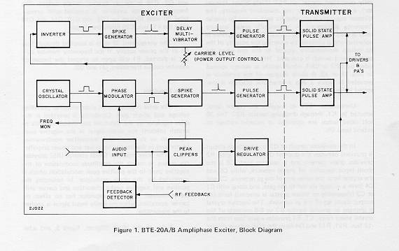
4. Ampliphase. A phase-modulated system developed by RCA where the transmitter developed two RF signals in the final, 135 degrees apart. To modulate the signal, the phase relationship between the carriers is varied, more toward 180 degrees would be a negative peak, and more toward 90 degrees a positive peak. These transmitters required less space and were more efficient than traditional plate-modulated transmitters. They required careful setup and tune-up to reduce distortion and somewhat unfairly earned the name “amplifuzz” from some engineers.
RCA BTE 20 ampliphase AM excit
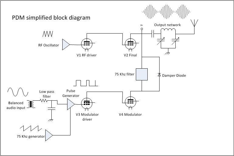
5. PDM or PWM. This is also a high-level modulation scheme but with some slight variations. The carrier power level and modulation levels are set by a PDM encoder card. In Harris transmitters, the PDM frequency was 75 KHz. The carrier is set by the amplitude of the PDM waveform, and the modulation is determined by the duration of the pulse. PDM transmitters require power supply voltages about twice the voltage of a standard high-level plate-modulated transmitter. They also require a damper diode to conduct the B+ voltage to back to the power supply during negative peaks, otherwise, the PA voltage will attempt to rise to infinity. I have found the damper diode to be the weak link in a tube-type PDM transmitter.
Solid state transmitters also use this design with either MOSFETs or BJT, which are then combined in parallel to generate the required output power. This is most often called “Class E” or something similar. In that system, each pair of modulator MOSFETs has its own fast-acting damper diode, usually protected by a fuse.
Harris MWx tube type PDM transmitter
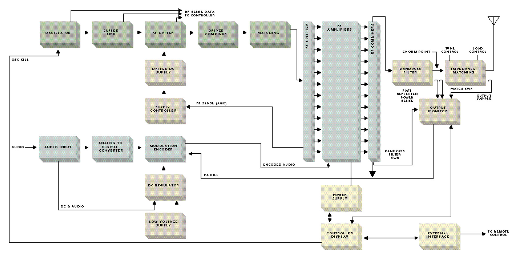
6. Direct Digital Synthesis. This is a patented design from Harris Broadcast used in their DX series transmitters. The incoming audio is sampled at either the carrier frequency or 1/2 the carrier frequency depending on where in the band the station falls. The solid-state PA modules are then switched on and off at the carrier frequency with the audio levels imposed on the carrier information. The explanation is simple, the application is complex:
Harris DX series AM transmitter block diagram
Of all these transmitters, the Harris DX series is the most efficient from a power input (AC) to power output (RF) perspective. There are several methods of reducing electrical use by reducing carrier power levels during lulls in modulation. The Continental 418E and later series transmitters can reduce carriers up to 6 dB using CCM. Harris and Nautel use similar systems on their DX and XL transmitters respectively. The wheatstone corporate blog has an article: Greener AM transmission Methods that details others.
As far as simplicity, serviceability, and rugged design, the high-level plate modulated transmitters cannot be beaten. Many Amateur Radio operators build these units from scratch using old parts, tubes, and other reused equipment readily available, often for free. I have, in fact, donated several 1 KW AM transmitters to ham radio operators over the years.
If I were to design a “transmitter of last resort,” to use in case everything else fails, it would look something like this:
813 Tube type 250 watt transmitter final813 Tube type AM transmitter modulator section
The disadvantage of that design is it requires a 2KV power supply, which has its own set of safety concerns. I might substitute 833s for 813s and use heavier iron in the modulation transformer. That way the transmitter could develop a 500 to 1,000-watt carrier. The great thing about tube transmitters is, given the right output components, they can be tuned into almost any load. They are also easily adaptable for emergency operation into temporary antennas.
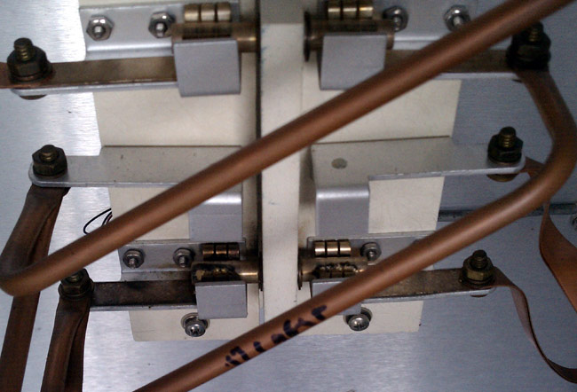
This is a set of burned contactor fingers on a Harris HS-4P 30 amp RF contactor:
Harris HS-4P RF contactor with burned finger stock
The back story is this:
The contactor in question is at the base of Tower #3 of the WBNR (1260 KHz, Beacon, NY) antenna array. This is the tallest of all the towers, at 405 feet. As such, it gets struck by lightning often. There was at least one occasion where one of the inductors in the ATU got “sucked in” due to the huge magnetic field of a high current strike. It is not at all surprising to me to find other component issues in this ATU. Because of the burned contacts, I’d suspect that the station was switching modes under power, but I didn’t see that happening today.
The problem manifested itself in very high SWR after changing over from day pattern to night pattern. This did not occur every time, in fact, it only occurred once in a great while at first. Then, over the last couple of months, it began occurring more and more often. Since the snow drifts are now down to a manageable six to eight inches, it was a good day to go out and do some exploring.
First of all, I put the station into nighttime mode just to confirm that there is still an issue. The transmitter, a Broadcast Electronics AM1A showed very high SWR and carrier fold back. Left it in night pattern, but turned it off and took a walk, not a drive, to Tower #4 which is all the way at the bottom of a hill, near the old City of Beacon landfill. I figured that I would check that one first, then look at Tower #3 on the way back. When I got to Tower #3, I found the issue right away.
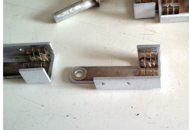
Fortunately, I was able to salvage a set of contact and contactor bar from another relay in the same ATU that was not using them.
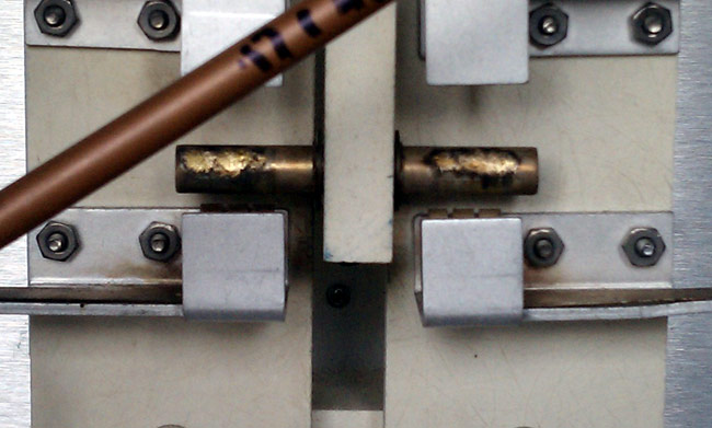
Burned RF contactor bar
The night pattern is only 400 watts, but these are tall towers, 225 degrees, therefore current and voltage are high at the base. In fact, the slightest change at the base of the nighttime towers will greatly upset things.
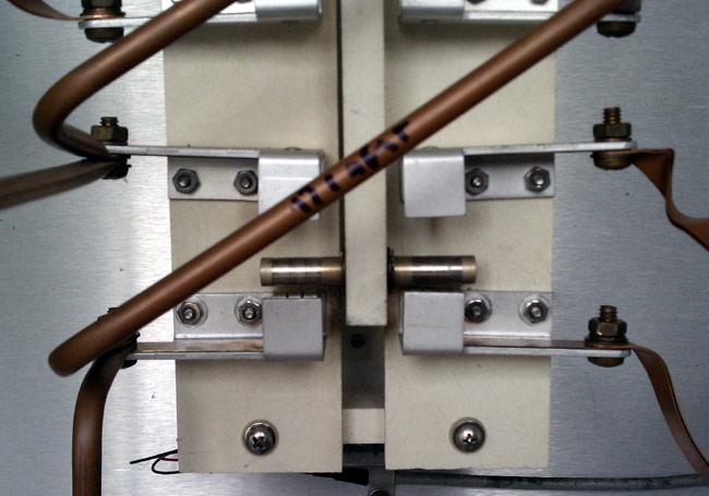
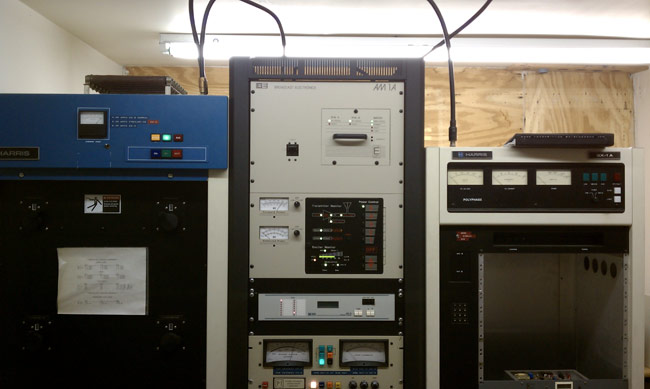
This is the repaired contactor. I will say, the EF Johnson RF contactors are easier to work on. Those are the ones with the big rocker bar across the top and two solenoids on either side. All of the wiring, status switches and contacts are exposed and easy to get to. This one, not so much. This is the BE AM1A transmitter
Broadcast Electronics AM1A transmitter
It is not a bad unit, compact, sounds good, is reliable, etc. In order to work on the power supply or anything in that top cabinet, the whole thing needs to be removed from the rack and taken down. I suppose that is my only gripe about the thing.