Update: WINE WRKI transmitter site move

I have been spending my days in Brookfield, Connecticut, dragging transmitters around and reconnecting them in various ways.  The WRKI-FM WINE-AM transmitter site is finally moving into the “new” transmitter building at the base of the tower.  Today, we moved WINE.

WINE was first signed on in 1963 on 940 KHz from a 170-degree non-directional tower on top of a pretty high hill.  That same tower serves as the antenna support for WRKI, which signed on in 1957.  The station runs 680 watts daytime, however since it is non-directional, it has some pretty serious power reductions at night.  The post-sunset power drops in two steps, 450 watts for the first hour, then 189 watts for the second hour, followed by 4 watts nighttime.

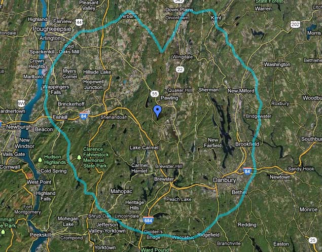
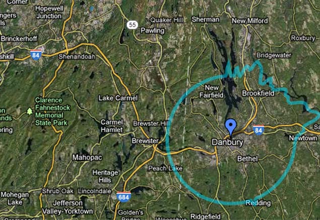
The 4-watt nighttime signal goes about 2-4 miles before it becomes unlistenable.  The Post Sun Set Authority (PSSA) allows the station to stay on the air with at least some coverage up to about 6:46 pm in the winter time and 10 pm in the summer, which is better than nothing.

The problem is, the Harris MW-1A transmitter goes down to 250 watts and no lower.  In order to make the nighttime power, the station switches to a dissipation network to burn off 246 watts of RF, at 50% percent AC-RF efficiency, which just ends up being a waste of power.  Further, the station engineers have been ignoring the PSSA because there are too many steps and it was easier to just switch to night power at sunset.

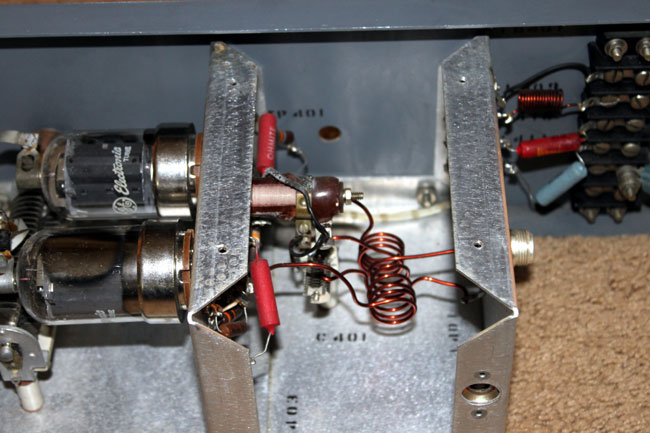
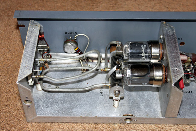
What we decided to do instead, was install a small low power night time transmitter, a Radio Systems TR-6000.  The MW1A can then be set to use the low power level for the first step of the PSSA, then switch the dissipation network in for the second step of the PSSA, and finally switch in the night transmitter at the proper time.

Harris MW1A AM transmitter, WINE 940 KHz, Brookfield, Ct

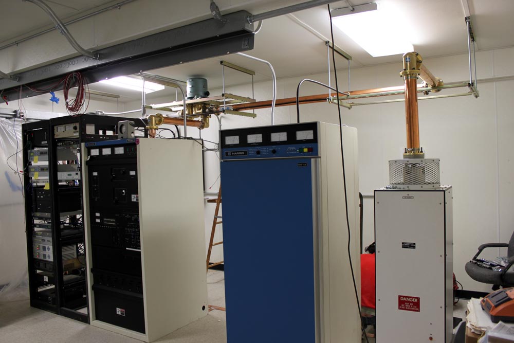
This is the Harris transmitter, new Circa 1981, which was cleaned up and moved into the new transmitter building.

WINE Parallel dissipation network and dummy load

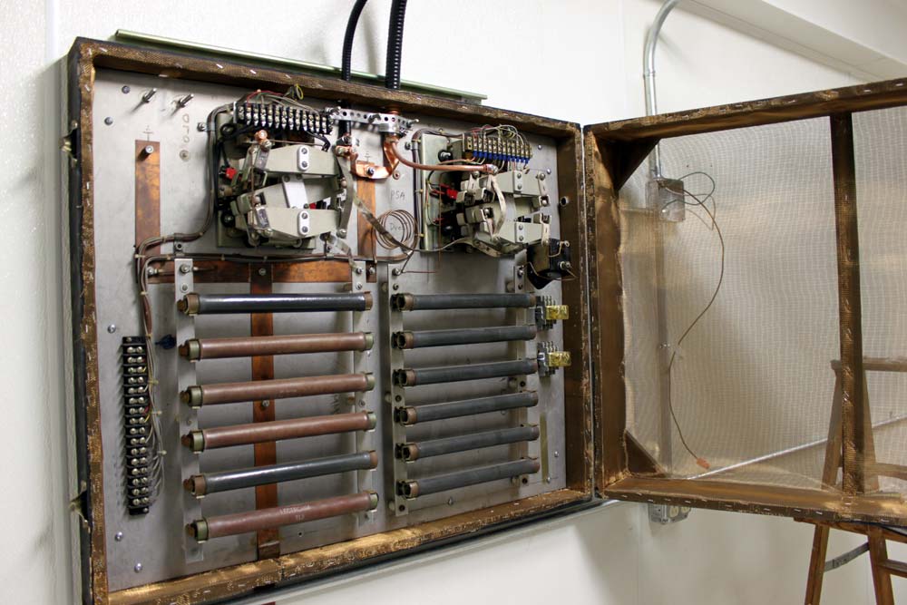
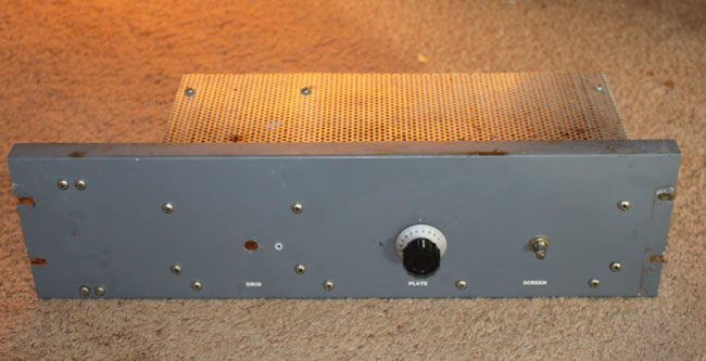
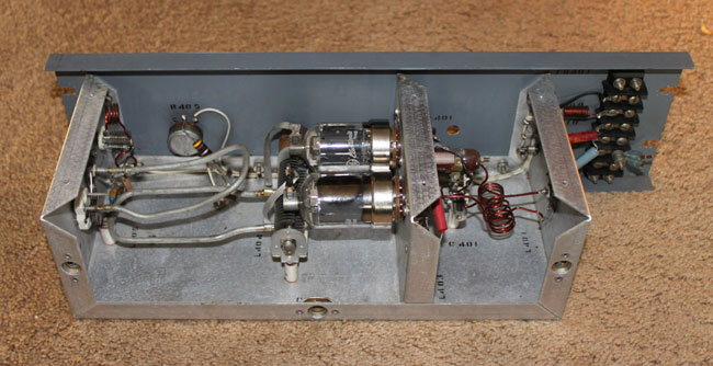
The dissipation network.  This will have to be reconfigured for the proper power levels, once the night transmitter is installed.  The dissipation network is on the right, a dummy load is on the left.  The two large RF contactors switch the dissipation network in and out, or select which transmitter is feeding the antenna/dummy load.  This is the really, really old school way of doing it.  Most transmitters manufactured after 1990 or so can run at any power level, making a dissipation network unnecessary.

Before re-installing the dissipation network/dummy load, we lined the enclosure with copper mesh.  I don’t want that thing interfering with any of the other equipment nearby, which would be the STL receivers, satellite receivers, or Town of Brookfield police dispatch radios.

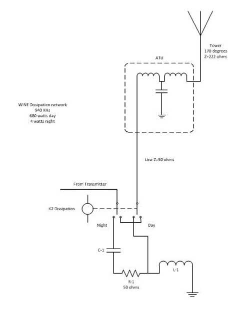
Schematically, it looks like this:

WINE 940 KHz Brookfield, CT night time dissipation network

This is the picture behind the transmitters, which shows the coaxial cable feed through ports and the dissipation network on the wall.

WINE WRKI transmitter room, behind the transmitters

It is a work in progress, so forgive the mess.

Synchronized FM signals

How effective are they at filling in or expanding coverage for FM stations?  The answer is, it depends.  Most have heard of the quadcast around New York City on 107.1 MHz formed in 1996-98.  It was well documented in Radio World and several other publications as a clever way to overcome the suburban rimshot problem.  Four signals on 107.1 were synchronized using GPS timing data, then fed the same program material.  They were WYNY, Briarcliff Manor, NY; WWXY, Hampton Bays (Long Island), NY; WWYZ, Long Branch, NJ; and WWYY Belvidere, NJ.  These being four separate Class A FM stations, the 60 dBu contours did not overlap.  There was some mutual interference in some areas, but there were few if any reception negative zones where the signal strength is equal between stations.

In early 2003, I was a part of the disassembly of the quadcast.  In the end, it is difficult to point to any one thing that leads to the breakup.  The station’s owners, Big City Radio, had filed for bankruptcy.  I am not sure if the company ever had the correct formula for marketing and sales, given the strong suburban, but weak and lacking building penetration in Manhattan signal.  The station initially had a country format, something that armchair quarterbacks said would not work in New York City.  After a few years, Big City changed the format to Rumba, a Spanish/Caribbean music format, which did worse than Country.  The fact is, that it never lived up to expectations and the station was worth more separately than together.  Given the right circumstances, it could have worked.

The other synchronized FM broadcasts are those where boosters are employed.  These are a good deal more difficult to configure because the booster signal is within the main station’s 60 dBu contour.  Often cases, where there is severe terrain shadowing or other limitations, a well-positioned booster that is in a population center can greatly improve the signal in those areas.  This was formerly the duty of an FM translator, however, those stations seem to be taking on a life of their own, without regard for the intent of the current FCC rules.  Boosters can also be called a single frequency repeaters or single frequency network (SFN).

The disadvantages of an SFN are the aforementioned negative reception areas.  To the receiver, this will create a multipath or picket fencing situation, which is objectionable to most listeners.  The advantages are, of course, better coverage in key areas, spectrum efficiency, and the ability to create a network of common frequency systems.  Think of how easy it would be if all NPR stations were all on the same frequency, for example.

The key to making a booster work is to synchronize several aspects of the RF and Audio signals:

  • RF carrier frequency
  • Stereo pilot frequency and phase
  • Audio amplitude and phase

The RF carrier frequency, stereo pilot frequency, and phase are locked with a GPS. Most transmitters have a 10 MHz or 1 PPS input for this.

The audio amplitude and phase synchronization are slightly more complicated. Basically, all of the audio should be coming from one audio processor and the path to the individual transmitter sites has to be very low latency. RF STLs work for this setup well, if there are suitable paths.

Once that is established, the audio timing is used to move the interference zone away from undesirable areas. There will always be an interference zone where both signals are received at the same relative strength causing dropouts.

WDBY, Patterson, NY 60 dBu contour

This is the situation with WDBY in Patterson, NY.  The main transmitter site is located on a hill in Patterson and has a power level of 900 Watts at 610 feet (186 meters) HAAT. The main population area is Danbury, CT, to the southeast, about 12 miles away.  Between the two, there are several imposing hills, which create reception issues in Danbury.  Therefore, WDBY FM1 was placed in service at the Danbury Medical Center.  The booster has a power output of 1,200 Watts, at 0 feet (0 meters) HAAT (49 meters AGL).

WDBY FM-1 signal, Danbury, CT 60 dBu contour

Therefore, the southern area of the 60 dBu contour is filled in by the booster.  The interference zone between the two transmitters is determined by the amount of delay in the audio between the two units.  If both are time the same, the interference will occur at precisely 1/2 the distance between the transmitter sites, which in this case is 10.18 KM from the booster.  Looking at the population maps, it might be better to move that more toward the north, away from Danbury.

The formula for computing audio delay time is:

A-B=C where A is the distance between the transmitters and B is the distance to the interference zone from any given transmitter.  The product of that is multiplied by a constant of 3.34 to obtain the time delay in microseconds.  Therefore, if the interference zone is desired to be further outside of Danbury, say 15 KM away, then the equation looks like this:

20.358 kM -15.0 kM = 5.358 KM

5.358 KM x 3.34 = 17.89 μS delay from the main transmitter site will put the interference zone out in the middle of nowhere, away from Danbury.  This is the total delay between the two stations, therefore any difference in STL paths needs to be included in this figure.

Nautel has a good webinar on SFNs which can be found on their website: Single Frequency Networks Webinar

Nautel equipment has most of these features built into it, therefore, the implementation of an SFN using Nautel exciters and transmitters should be relatively straightforward.

Conduit fill

It may be surprising to some, but the number of wires allowed in any given conduit is not “as many as can be jammed in there.” The National Electrical Code, AKA NEC or NFPA 70 gives specific guidance on the number of current-carrying conductors allowed in any specific size and type of conduit.

This is due to the fact that current-carrying conductors generate heat.  Cables enclosed in a conduit need to dissipate that heat so that the insulation on the cable doesn’t melt, which would be a bad outcome.

Conduit fill tables are found in Chapter 9 of the NEC.  There are several tables that give the number of conductors for each size and type of conduit.  Then there is the general rule of thumb that for more than two cables, the maximum conduit fill is 40%.  This comes in handy when several different size conductors are being run in the same conduit.

An example of this is when several circuits are going across the room to the same general location, in this case, a row of transmitters and racks.  Instead of running individual conduits for all those units, one or two conduits from the electrical panel are run to a square wireway, then the individual circuits are broken out and wired from wireway to the individual loads.  In this case, the following equipment is being connected:

  • Harris FM25K: 100 amp 3 phase high voltage power supply (#2 THHN), 30 amp 3 phase transmitter cabinet (#10 THHN)
  • Harris FM3.5K: 70 amp split phase (#6 THHN)
  • Harris MW1A: 30 amp split phase (#10 THHN)
  • Two equipment racks: 20 amp single phase (#12 THHN)
  • Coax switch: 15 amp single phase (#14 THHN)
  • Dummy Load: 15 amp single phase (#14 THHN)
  • Antenna switch/dissipation network for AM station: 15 amp split phase (#14 THHN)
  • Convenience outlets for the back wall: 20 amp single phase (#12 THHN)

Excluding grounding conductors, which will be addressed below, the total current carrying conductor count is thus:

  • #2 THHN: 3 each
  • #6 THHN: 3 each
  • #10 THHN: 7 each
  • #12 THHN: 6 each
  • #14 THHN: 6 each

Ampacities based on NEC table 310.16, THHN insulation in dry locations, maximum temperature rating is 90° C (194° F) based on the ambient temperature of 30° C (86° F)

Grounding conductors for each of those circuits, based on NEC Table 250.122 (all conductors are copper):

  • 100 amp circuit: #8
  • 70 amp circuit: #8
  • 30 amp circuit: #10
  • 20 amp circuit: #12
  • 15 amp circuit: #14

The final conductor count is:

  • #2 THHN: 3 each
  • #6 THHN: 3 each
  • #8 THHN: 2 each
  • #10 THHN: 9 each
  • #12 THHN: 9 each
  • #14 THHN: 9 each

The plan is to use two 1 and 1/2-inch EMT conduits between the electrical service panel and the 4 x 4 square wireway. According to  NEC Chapter 9, Table 4, the 40% cross-sectional size of this conduit is 526 mm2.  It is easier to simply use metric measurements for this.  The cross-sectional wire areas are found in Chapter 9, Table 5.  Chart of various conductor sizes and areas:

ConductorArea (mm2)Total conductorTotal area (mm2)
#2 THHN74.713224.13
#6 THHN32.71398.13
#8 THHN23.61247.22
#10 THHN13.619122.49
#12 THHN8.581977.229
#14 THHN6.258956.322

Thus, in order to break this up into two 1 and 1/2-inch conduits, the #2, #6, and #8 (main transmitter HV power supply, backup transmitter, and grounds) are run in one conduit, the remaining circuits in the other.  The idea is that the main transmitter and backup transmitter will not be running simultaneously for long periods of time.  Those cable areas total 369.48 mm2, well within the 40% limit of 526 mm2 for 1 and 1/2 inch EMT.   The rest of the circuit’s cable areas total 256.041 mm2.  That leaves room for additional circuits in the second conduit if future needs dictate.  The extra conduit area will make pulling the wires through easy.

From the square wireway to the HV power supply, 1 and 1/4 inch conduit will carry the three #2 and one #8 ground.  1 and 1/4 inch EMT has a cross sectional area of 387 mm2, the conductors contained within will be 271 mm2.  Less room here, but still well within the 40% limit.

Pictures will be posted when the project is done.

The Gates BFE-50C Amplifier

Found in a pile of junk in the corner of an older transmitter site, this Gates BFE-50C or otherwise known as an M5675 Amplifier. This was used as an IPA in a Gates FM 1C transmitter installed around 1960 or so.  The rest of the transmitter has long since departed, likely to the scrap yard, however, somebody thought to remove this and set it aside.

Gates BFE-50C 50 watt VHF amplifier
Gates BFE-50C 50 Watt VHF amplifier

This unit is missing it’s grid tune knob.  The grid tune capacitor is still there, however.  There is also some evidence of heating on R403 and R407/408 likely due to a prolonged overdrive condition.  Otherwise, it is in good shape.

Gate BFE-50C 50 Watt VHF amplifier back

The design is pretty simple, a pair of 6146’s in push pull, three watts in nets about 50-60 watts out, according to the manual, which can be found here (.pdf).  The power supply voltages are fairly tame, 500 volts plate, 300 volts screen.  The one thing that this design does not have is any type of harmonic filtering.  When used with a larger transmitter, this makes sense because the transmitter output will have overall harmonic filters.  If this was to be used on it’s own for any reason, a good harmonic filter would need to be designed and installed.

Gates BFE-50C or M5675 50 watt VHF amplifier
Gates BFE-50C or M5675 50 Watt VHF amplifier

The schematic is straight forward.  Gates, the old Gates Radio of Parker Gates, designed good equipment.  Click on image for higher resolution.

Gates BFE50-C input section

It is a bit hard to see in this picture; the input section consists of three turns of #14 gauge wire coupled to two 4 turn sections of 14 gauge wire on either side of it.  This is matched to the grids Screen1 of the 6146s with C401.  L412, C411 and L413 form a low pass filter.  L412 consist of one turn #14 gauge wire, L413 is five turns of #14 gauge wire.  All coils are 3/4 inch in diameter.

Gates BFE-50C output section

The output section is even simpler, using just one loop of small diameter copper tubing.  The plate tuning is accomplished by C407, loading is C406.  Power output is adjusted by varying the screen voltage using R405.

Advantages of this design:

  1. The 6146 tube is fairly rugged, at class AB the 50 to 60 watt output range is well within the plate dissipation for a push pull configuration.
  2. No special parts are needed, everything can be found or fabricated by hand
  3. The 500 volt supply is fairly tame, maximum PA current should be less than 0.2 amps for 50 watt output and 50% PA efficiency.
  4. Output tuning and load allow for tuning into less than ideal loads, if required.
  5. If operated as a stand-alone unit, some type of plate current meter should be used to aid tuning.  A harmonic Filter would need to be designed and built for the output.
All in all, a pretty cool little FM amp.