How much is prevention worth?

I sometimes get the distinct impression that the corner office doesn’t understand what it takes to keep a radio station on the air and in good repair.  It is most often the problems or “issues” that tend to get the most attention.  The things that are working well tend to get ignored. After all, how often do you hear a news report about the airliner that landed safely?

Lightning strike TV tower
Lightning strike, TV tower

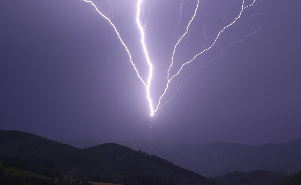
When lightning strikes the tower and knocks the transmitter off the air causing major damage and expensive repairs, that is a problem.  When lightning strikes the tower and nothing happens, no problem.  What is the difference between those two situations?

Grounding strap, FM transmitter site

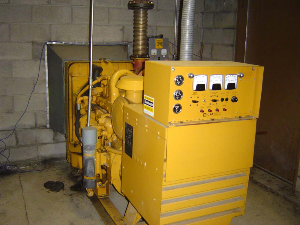
If the generator starts and runs during every power outage and has done so for the last five years straight, it is obviously a reliable unit, does it need all that maintenance?

Caterpillar 75 KW diesel GENSET

Money spent on preventing undesirable outcomes can be difficult to quantify as disasters and events that do not happen are ill defined.   It is difficult to quantify the “amount saved” on something that didn’t or won’t occur.  Using past situations is good start, but that only covers a fraction of possible outcomes.  In order to invest money wisely, one has to look at the probabilities.  If there is an unlimited budget, then the probability exercise should be minimal, however, there is very seldom an unlimited budget.

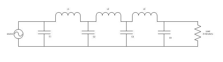
For example, how much does a back up STL system cost vs the risk of being off the air while the main STL system is being repaired?  How often do failures occur, when are they likely to occur and for how long are all good questions.  Is there an alternative to a full backup like an IP CODEC?  Such a solution would cover all aspects of the STL system including antennas, transmission line, transmitters and receivers.

There are certain FM stations north of here that have neither RADOMES or antenna heaters.  Once every two years or so, the antenna ices up and the transmitter folds back due to VSWR.  How much of an impact to listeners notice when this happens?  If it happened more often, say two to three times a year, would it be wise to invest in some type of deicing equipment?

What is the ownership and management opinion on off air conditions?  I have often heard tell “Oh, its only the AM, we don’t mind if it goes off the air.”  That is, until it actually goes off the air, then it is a big problem.

Based on my and others experiences, these are the things that will happen at an average transmitter site:

  • The electricity will go off at least once per year for several hours.
  • The main transmitter will fail at least once every two years.
  • Lightning will strike the tower at least once per year.
  • The STL system will fail, at unknown intervals.

At studio sites, these things will occur:

  • The file server will crash depending on the operating system
  • The telephone lines and or T-1 service, internet service, ISDN etc will go out
  • The electric power will go out for several hours
  • The satellite dish will fail once every two to three years
  • If there is a tower, it will get struck by lightning

Other site specific things can occur like floods, blizzards, earthquakes, fire, etc.

Money spent on backup systems for those items is good insurance.  Not only will the station stay on the air, the on call engineer’s phone will ring less often, which, if you are the on call engineer, should make you happy.

If a full backup is not available, a second transmitter for example, having a good stock of spare parts on hand can mean the difference between an early evening and an all nighter.   Keeping good maintenance logs and well documented repair records can point out trends and give a good basis for ordering spare parts.

Repair trends are important.  If the same part seems to be going bad over and over, it is time to dig deeper and find the cause of failure.

The old adage “An ounce of prevention is worth a pound of cure,” still holds true.

The Harris MW1A

They say the first thirty years are the hardest, perhaps it is true. This Harris MW1A transmitter turns 31 this year:

Harris MW1A AM transmitter, WINE, Brookfield, CT

Truth be told, these are not bad units.  They have some quirks, however, the overall circuitry is simple, the design is simple enough and parts for repair are readily available.  They require regular infusions of RF transistors, but those are easy to change and are inexpensive to buy off the shelf from places like Mouser or Allied.

It is on the air as the main transmitter for WINE-AM in Brookfield, CT.   This is Harris’s first solid-state AM transmitter design, based on the work of Himmler Swanson.  This is not a PDM transmitter, rather, each module has RF transistors and audio transistors.  The output of all twelve modules is combined for a carrier output of 1,000 watts with +125% modulation.   Harris calls this PSM (Progressive Series Modulation), which is sort of high-level modulation.

This is also the only transmitter that I know of where blown fuses can cause damage to the RF devices.

The RF output transistors and audio transistors are still available from Harris.  Non-OEM parts for this include the 2N5038G for the RF transistors and the MJ15011 for the audio transistor.  Inside the front of the transmitter is a row of incandescent light bulbs that glow increasingly as the various transistors go bad.  At 1,000 watts carrier power, the ratio of PA volts to PA amps is 52.5/22.5 respectively.  If that ratio is off by any measure, there is a problem.

Original sales brochure for the MW1 (no A):

Harris MW1 sale brochure

Entire brochure is available here.

Harris MW1 interior view

The other thing with this transmitter is it is very sensitive to any kind of VSWR.  Any change in the output impedance will quickly make itself apparent.  My Harrisburg MW1A had two ATU settings, one for winter and one for summer.  It was a slightly tall tower on 1230 KHz, thus any change in the ground system (e.g. snow cover) would upset the tower base impedance.

The other thing that goes bad is the large Rotron fan at the bottom of the cabinet.  They go bad about every 10-15 years or so.

The owner has spent some money on this particular unit, rebuilding and replacing several modules with new transistors, etc.  Will it last another thirty years?  Depends on if the RF and audio devices remain in production.

WRKI WINE transmitter move, update 2

Man, this is taking longer than I thought it would. We moved the Harris FM25K last week, all went well. The only hangup, as you can see, is the harmonic filter and the height of the racks next to the transmitter. The transmitter had to go on a 4×4 to get the filter up over the racks. The output from the transmitter to the harmonic filter cannot be changed in any way, shape, or form (e.g. adding a little bit of line section to the top of the transmitter), or else the transmitter will not run. So, up on 4×4’s it is.

WRKI WINE transmitter room

There we were, all ready to turn the transmitter on.  Press the high voltage on button, lots of volts but no current and no power output.  Seems something is wrong with the outboard IPA driver (over in the bottom of the rack, that thing pulled out with the manual on it).

The IPA is a Silicon Valley Power Amplifier 500-watt unit, which replaced the internal IPA driver about ten years ago.  The tube in the Harris FM25K needs at least 390 watts to drive the transmitter to full power.  Unfortunately, this particular amplifier was not in the best environment prior to the recent move.  It was sitting in an unconditioned building on top of the backup transmitter in high heat and humidity.  According to the manufacturer, such abuse is bound to take its toll sooner or later. The latter being, of course, the night we want to turn the thing back on and go home.

Time to drop back and punt.  I found an old RVR 250-watt amp at a sister station nearby, which was also in pretty bad shape but repairable.  That unit was pressed into service temporarily and with 200 watts drive, the old 25K put out about 11 KW.  We need to affect permanent repairs to the RVR power amp before we place it into temporary service.  I don’t want any 2 am phone calls.  The Silicon Valley Power Amp needs to have the amplifier module sent back to the manufacturer and rebuilt.  They will refurbish the entire thing for something like $900.00 plus shipping.  Considering what it does, that is worth it.

This is a little short cellphone video of the turn-on at half power.  This is a very loud transmitter, as such, I think the audio is a little distorted.

When this beast gets up to full power, I will update this, again.

Low Pass Filter design

Every good transmitter, tube transmitters, in particular, require harmonic filtering.  The last thing any good engineer or broadcaster wants is to cause interference, especially out-of-band interference to public safety or aviation frequencies.  All modern transmitters are required to have spurious emissions attenuated by 80 dB or greater >75 kHz from the carrier frequency.  In reality, 80 dB is still quite high these days, especially in the VHF/UHF band, where receivers are much more sensitive than they used to be.  A good receiver noise floor can be -110 dB depending on local conditions.

The principle behind a low pass filter is pretty easy to understand.  The desired frequency is passed to the antenna, while anything above the cut-off frequency is restricted and shunted to ground via a capacitor.

Low pass RC filter
Low pass RC filter

In this case, the resistor is actually an inductor with high reactance above the cut-off frequency.  Often, these filters are lumped together to give better performance.  This is a picture of an RVR three-stage low pass filter:

RVR three stage low pass filter
RVR three-stage low pass filter

RVR is an Italian transmitter maker that sells many transmitters and exciters in this country under names like Bext, Armstrong, etc.  The inductors are obvious, the capacitors consist of a copper strip sandwiched between teflon insulators held down by the dividers in between the inductors.

Schematically, it looks like this:

Low pass filter schematic diagram

For the FM broadcast band, a good design cutoff frequency would be about 160 MHz. This will give the filter a steep skirt at the first possible harmonic frequency of 176 MHz (88.1 x 2 = 176.2).

Values for components:

CapacitorsValueInductorsValue
C120 pfL174.7 nf
C254 pfL275.1 nf
C354 pfL373.9 nf
C420 pf  

The inductors are wire, or in this case copper strap, with an air core.  It is important to keep the transmitter power output in mind when designing and building these things.  Higher carrier powers require greater spacing between coil windings and larger coil diameters.  This particular filter is rated for 1 KW at 100 MHz.