A client of ours, WDST in Woodstock, NY, has this Best FE7KVA UPS. This unit is several years old and has already been through a couple of battery replacements. These are good units, however, Best Power has been bought up by Eaton/Powerware and they are no longer made apparently are still made.
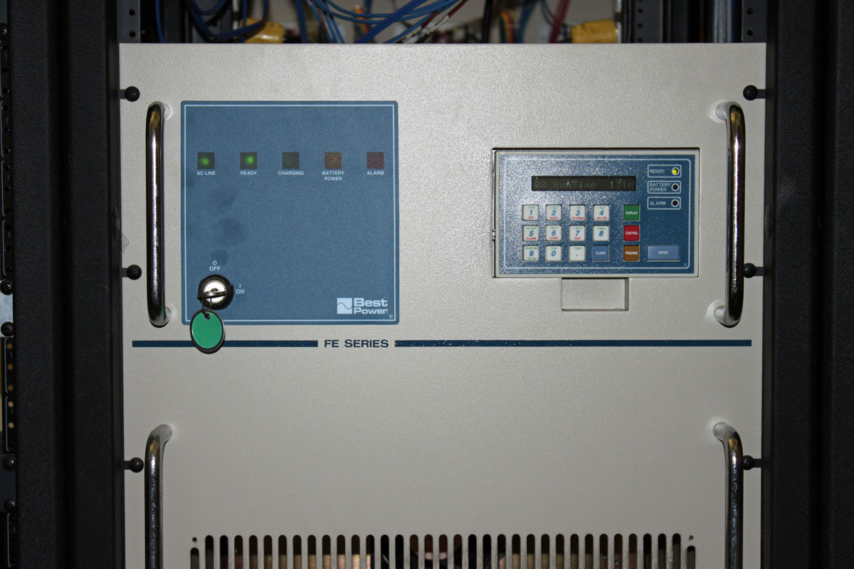
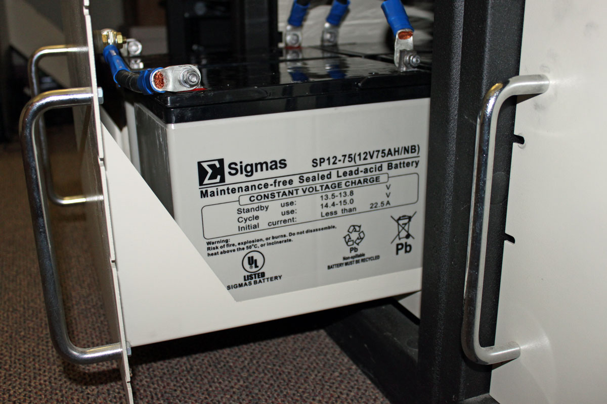
Regardless of that, the UPS is still functional, but like all UPS’s, it needs battery replacement every so often. This unit has three battery cases, each holding four 75 Ah (20 hour rate) 12 volt sealed lead acid batteries. Each battery is slightly larger than an average car battery. There is one important detail here, the batteries must be gas recombinant because the UPS has a four stage battery charging system. Gel or AGM batteries will not make it past the first or second equalizing charge.
A bit about batteries and battery charging. Most battery chargers are three stage units; bulk, absorption, and float. The rate of charge depends on the voltage of the battery. Bulk charging sends the most current to the battery and for 12 volt cells, this anything below 12.5 volts or so. Absorption stage reduces the charging current and supplies a steady current until the battery reaches full charge of 13.8 volts or so. Float or trickle charging draws very little current, just enough to maintain the battery at full charge.
The forth stage of charging is equalizing which is important for multiple battery series/parallel installations. This is when the batteries are deliberately overcharged for a period of time. The reason for equalizing charges is to intentionally boil off some hydrogen gas and knock any sulfur crystals off of the lead plates. With multiple battery banks in a parallel configuration, it is important to maintain the battery resistances as close as possible so that each bank of batteries is drawn on and charged equally.
In flooded lead acid batteries, this works well and the battery either vents off the hydrogen gas or recombines it will oxygen to make water again. In non-gas recombinant cells, the hydrogen will be released into the room which may pose an explosion hazard. Additionally, the electrolyte level will need to be checked after every equalization charge. With a sealed non-recombinant battery, the case my bulge and split, spilling electrolyte and ruining the battery and battery enclosure. Thus the importance of ordering the correct replacement batteries.

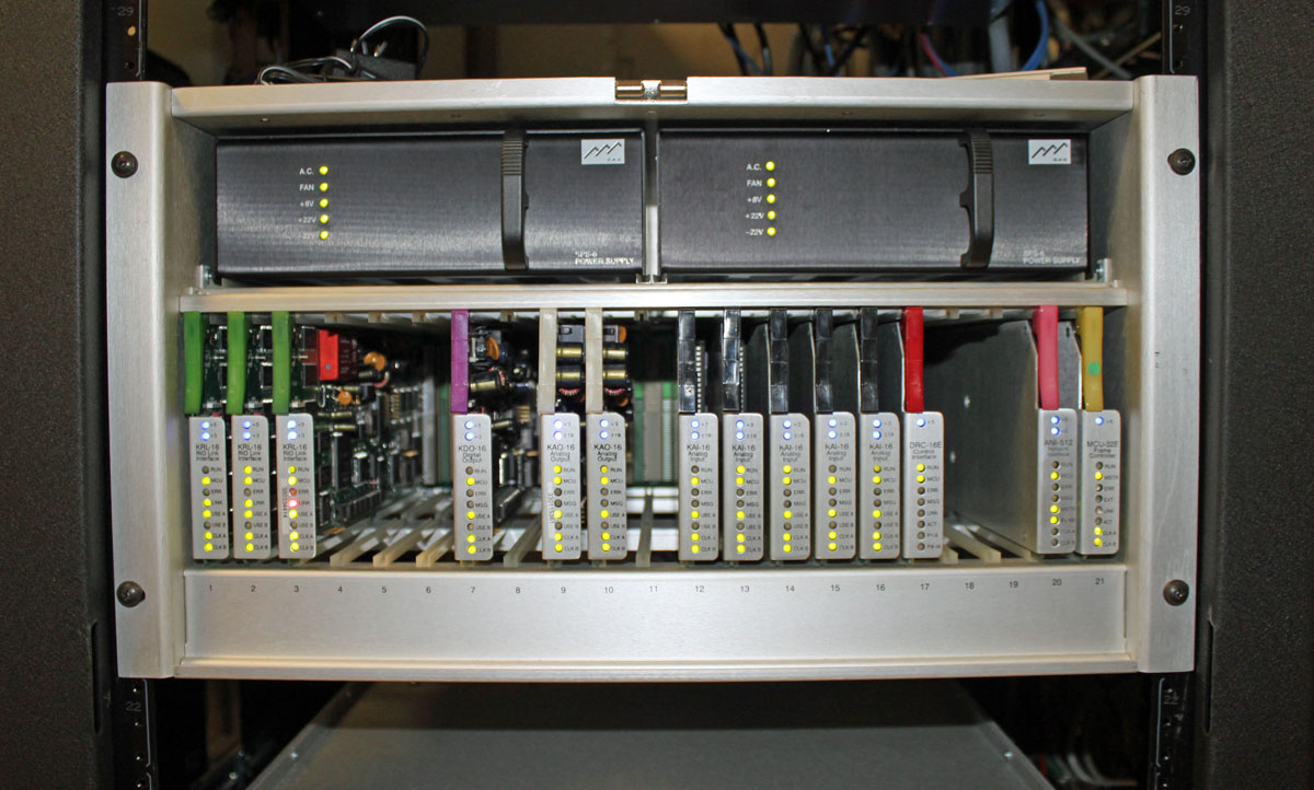
After all, the reason for the UPS is to protect the expensive computer equipment connected to it. It simply will not do to install the wrong stuff and do more damage than if the UPS did not exist at all.