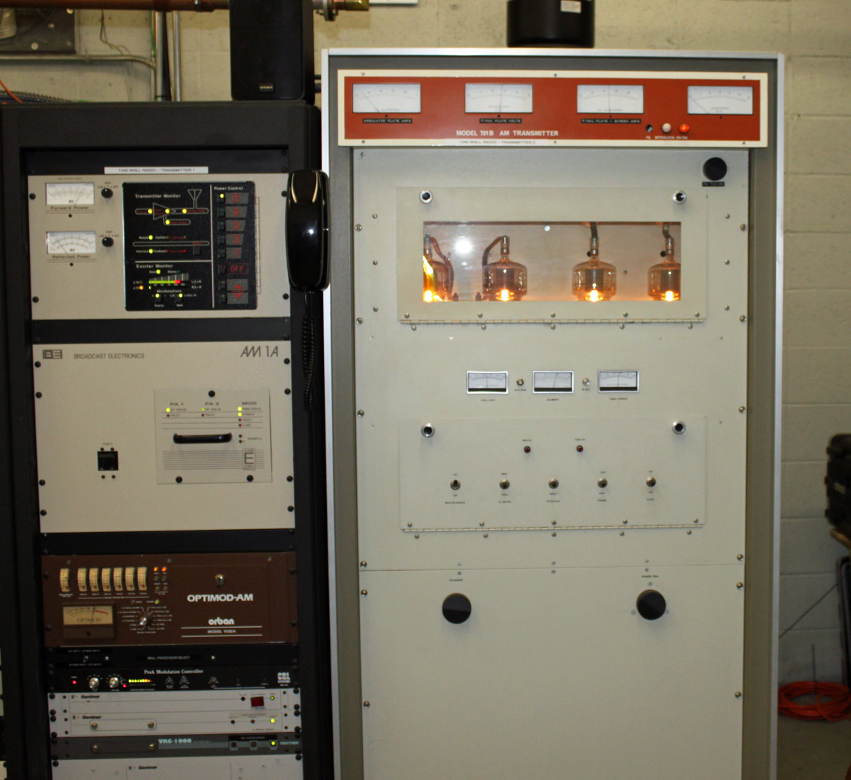
In service as a backup unit at WALL 1340 KHz in Middletown, NY:
WALL 1340 KHz, Middletown NY AM1A on air, 701B into test load
I believe the Cetec transmitter is from the early 70s. I wouldn’t really call it old, we have much older units in the field that are still in backup service. WALL itself has been on the air since 1942 from this site. The tower out back was replaced in the mid ’90s and is 147 degrees tall. It broadcasts the “True Oldies Channel” and is currently owned by Cumulus, soon to be Townsquare.
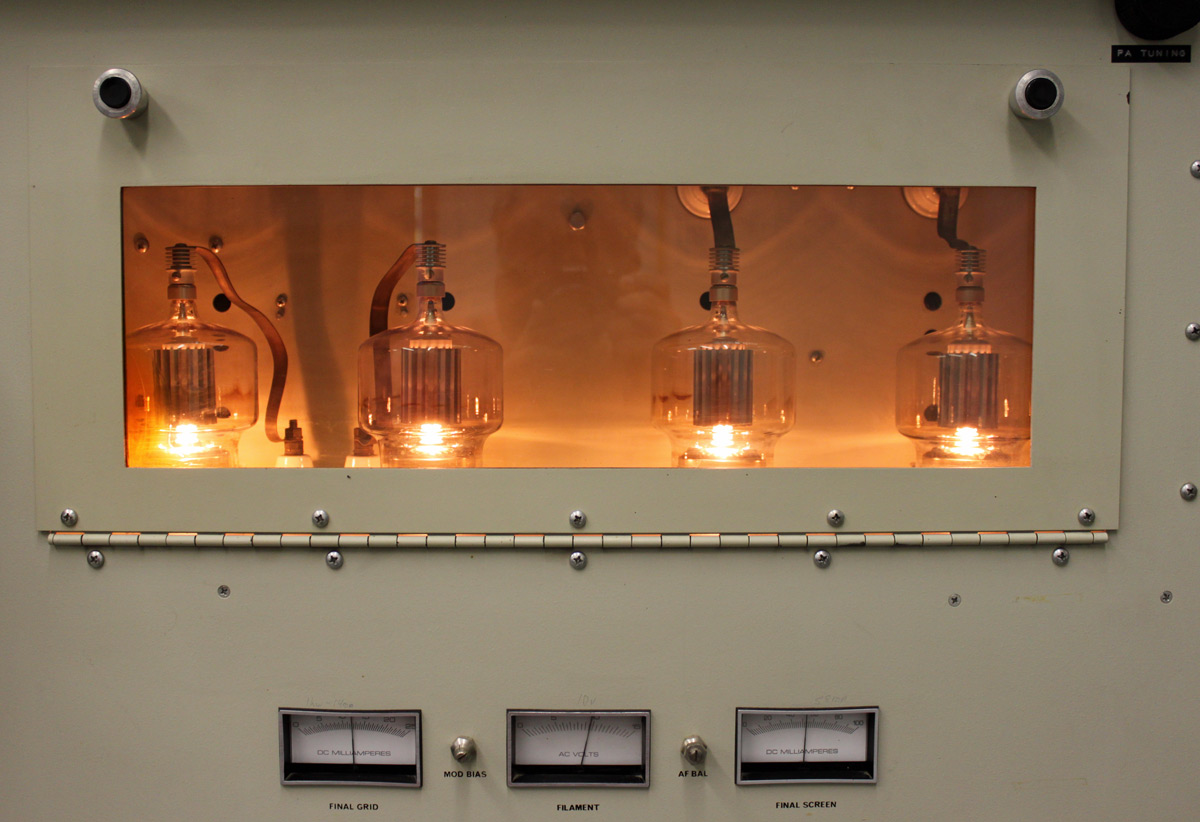
Cetec 701B tube deck. 4-500As.
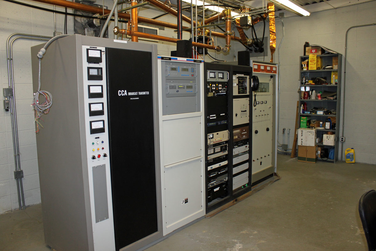
The site is also home to sister station WRRV (92.7 MHz) which has a side mounted antenna near the top of the WALL tower. We are currently reconnecting the CCA transmitter as the backup for WRRV. That unit is also from the early 1970’s.
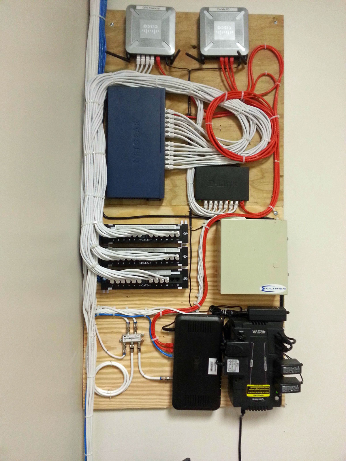
In the comments, he gets blasted for being too neat and using wire ties. I know a lot of IT guys that are not very neat with their work and document nothing. This is a big problem in the industry and does not, contrary to popular belief, promote job security. I have walked into some very messy situations in wiring closets and rack rooms over the years. My solution is always the same; run some temporary wires for critical machines/functions, then get out the big wire cutters and start chopping.
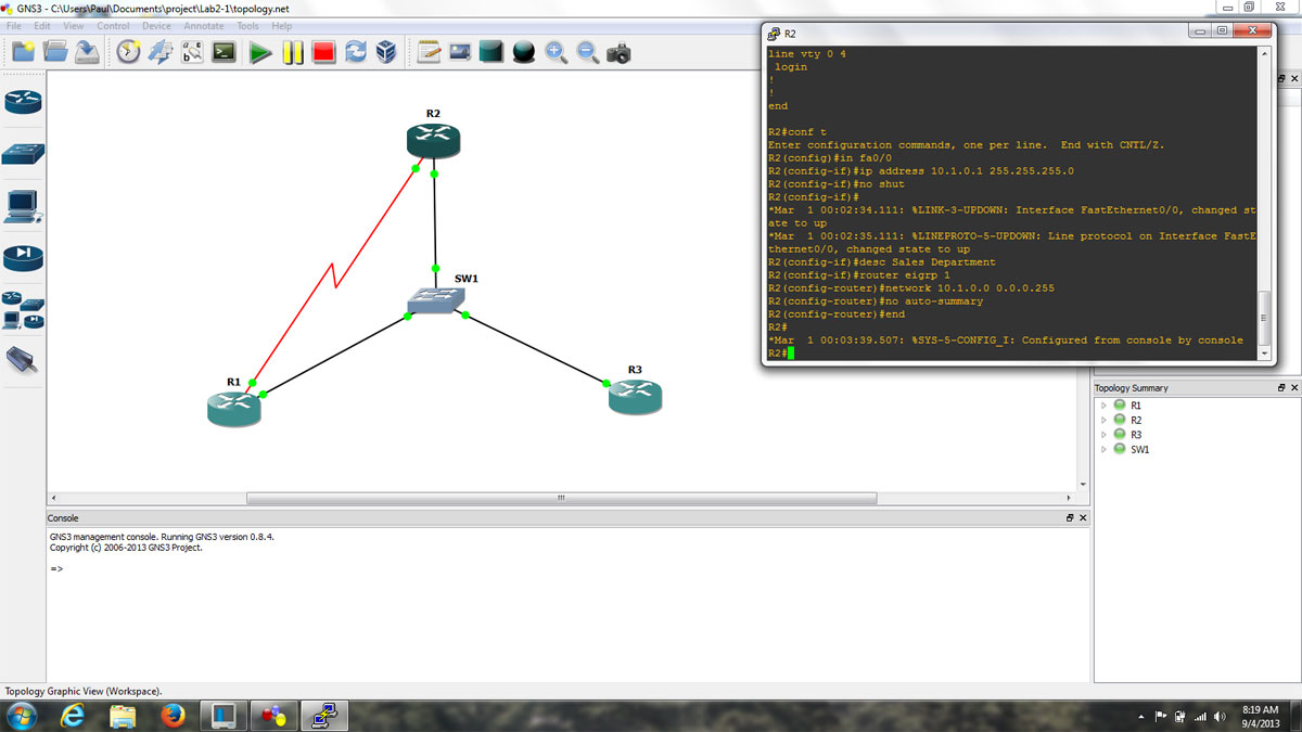
I have been working with GNS3 (Graphical Network Simulator) in some of my classes. It is a fine tool with which one can build simulated computer networks using various routers and switches. The software program itself is free, however, the Cisco IOS images are not included and must be found elsewhere due to copyright issues. This detail is a bit of a pain, but not too bad. Once the program is set up and the appropriate IOS images are loaded, the console functions exactly like whatever router is being simulated. This includes running whichever terminal program is preferred, e.g. hyperthermia, putty, or if using the Linux version, x-term, etc.
GNS3 screenshot, topology, and router console
The advantages to this over something like Cisco’s Packet Tracer program are many. In Packet Tracer, certain functions are locked out and generally there is only one acceptable way to complete any given task. With GNS3, the IOS is fully functional, which means that experimentation and failure are available to play with. Failure is a great way to learn things in any hands-on environment. The advantage of virtual failure is that only you know about it.
For real-world applications, this means that router and switch configurations can be created, tested, and tuned ahead of time and then loaded into working devices, saving downtime and potentially handfuls of hair.
A few things about using GNS3, the PC idle tuning is required. Each instance of IOS assumes that the entire processor is available to use, thus starting several routers can work a PC’s processor to 100% and windows will never fully recover. Secondly, when starting each router, wait 10 to 20 seconds before starting another one. Again, this has to do with the way IOS uses processors. Also, to save time, store the IOS image as a decompressed file. This saves quite a bit of time on startup. Finally, do not forget to copy the running config to startup-config. Even though GNS3 says it is saving the router configs, it does not save the running config unless you issue the copy run start command, just like a real router.
Update: Apparently this is quite interesting to a number of people. I have rescanned the manual, properly compressed it and which you may find it here.
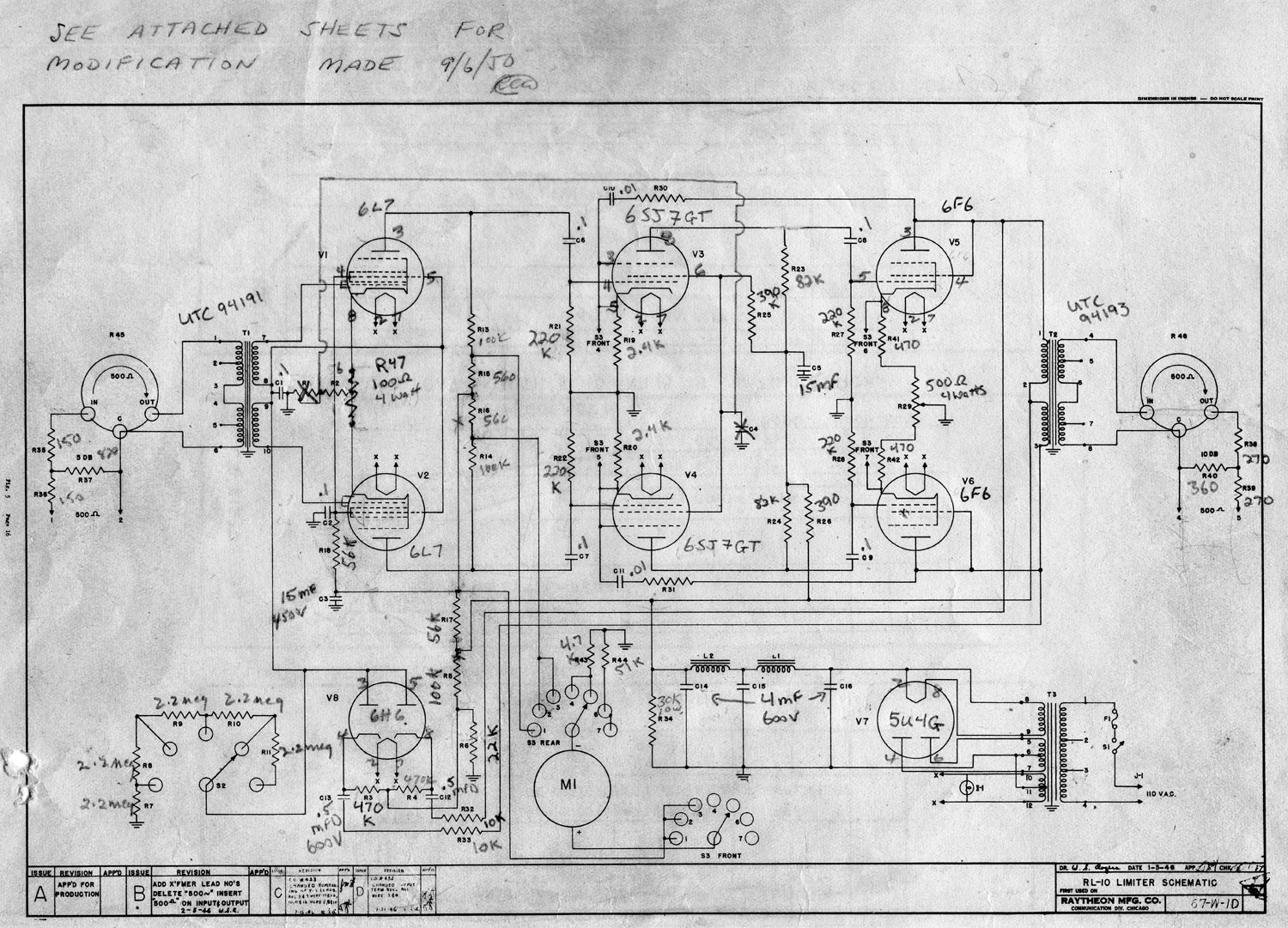
Found this manual at one of the older transmitter sites:
As this is an older design than either the Gates Sta level or the Collins 26U, it may not be as useful to tube audio enthusiasts.
Raytheon RL-10 Schematic diagram
The main issue with the Gates and Collins unit is the GE 6386 remote cutoff triode used, which were great tubes, but very difficult to come by these days. This design calls for a 1612 or 6L7, which is a pentagrid amplifier. Feedback is provided by the screen of the following stage, a 6SJ7GT. Anyway, perhaps it will give somebody some idea of how to make a good tube compressor limiter.