Network Data Flow Analysis

PRTG network sun
PRTG network sun

As more and more broadcast facilities are moving toward IP data for all types of data transfer including digitized audio, video, telephony, documents, email, applications, and programs.  Managing an IP network is becoming more and more important.  In most broadcast facilities, Ethernet-based IP networks have been the normal operating infrastructure for email, printing, file sharing, common programs, file storage, and other office functions for many years.  Either directly or indirectly, most broadcast engineers have some degree of experience with networking.

With many more IP-based audio consoles, routing systems, STL’s and other equipment coming online, understanding IP networking is becoming a critical skill set.  Eventually, all distribution of content will transition to IP-based systems and the current network of terrestrial broadcast transmitters will be switched off.

The difference between an ordinary office network and an AoIP (Audio over IP) or VoIP network is transfer consistency.  In an office network, data transfer is generally bursty; somebody moves a file or requests an HTTP page, etc.  Data is transferred quickly from point A to point B, then the network goes back to its mostly quiescent state. In the AoIP environment, the data transfer is steady state and the data volume is high.  That is to say, once a session is started, it is expected to say active 24/7 for the foreseeable future. In this situation, any small error or design flaw, which may not be noticed on an office network can cause great problems on an AoIP network.  The absolute worst kind of problem is intermittent failure.

Monitoring and analyzing data flow on a network can be a critical part of troubleshooting and network system administration.  Data flow analysis can discover and pinpoint problems such as:

  • Design flaws, infrastructure bottlenecks and data choke points
  • Worms, viruses, and other malware
  • Abusive or unauthorized use
  • Quality of Service (QoS) issues

Cisco defines flow as the following:

A unidirectional stream of packets between a given source and destination—both defined by a network-layer IP address and transport-layer source and destination port numbers. Specifically, a flow is identified as the combination of the following seven key fields:

  • Source IP address
  • Destination IP address
  • Source port number
  • Destination port number
  • Layer 3 protocol type
  • ToS byte
  • Input logical interface

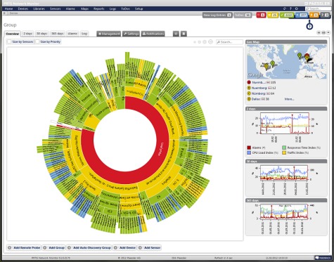
Packet sniffers such as Wire Shark can do this, but there are far better and easier ways to look at data flow.  Network monitoring tools such as Paessler PRTG can give great insight as to what is going on with a network.  PRTG uses SNMP (Simple Network Management Protocol) on a host machine to run the server core and at least one other host to be used as a sensor.  There are instructions on how to run it as a virtual machine on a windows server, which would be the proper way to implement the server, in my opinion.

For small to medium installations, the freeware version may be all that is needed.  For larger networks and major market installations, one of the lower-cost paid versions may be required.

Exploding Parts

We or rather, I have been working on installing this CCA transmitter as a backup unit at one of our sites. It was installed as a backup at another site but was mothballed about ten years ago. Now, we need to get it running again and re-tune it. Seems like a fairly uncomplicated job.

CCA FM-5000DS transmitter, circa 1971

Except, every time I start it, another one of these 1000 pf bypass/feed-through capacitors fails. They are located at various points around the PA enclosure and route AC voltages into and out of that enclosure.  The bypass function is needed to keep stray RF off of the control circuits. Normally, they have been failing with a medium resistance fault (40-70 ohms) to the case.  That causes the control circuit breaker to trip.

This time, however, it was on the primary for the filament transformer on the IPA tube.  Just a wee little pop, followed by some ozone smell and sans power output.  I have, thus far replaced four of these and there are seven originals still in the transmitter.

Feedthru capacitors
Feedthru capacitors

It is time to replace them all, otherwise, this rig will fail when we need it the most.  The replacement part is a Mouser 800-24437X5S0102MLF, 1000 pf 500 v made by Tusonix Electronics.

WROW

WROW 590 KHz, Albany, NY is another one of those successful AM stations.  They have a music format, which I would characterize as a blend between nostalgia and oldies.  They do well in the Albany book and most importantly; make money.  The Wikipedia entry is a little dated, as they have had a music format for over four years now.  The low dial position helps, as I can get the station up near the Canadian border and most of the way down to Poughkeepsie during the daytime pattern operation, which is better than across-town WGY, 50,000 watts non-directional.

Here are a few pictures of the transmitter site:

Broadcast Electronics AM5E, WROW, Albany, NY

WROW main transmitter

WROW transmitter room

WROW transmitter room; main and backup transmitters, phasor, equipment rack, etc.

RCA BTA1AR former backup transmitter

The former backup transmitter for WROW-AM. This was moved from the original transmitter site, located a few miles north of the current transmitter site in Glenmont, NY. The current transmitter site was constructed in 1974.

Onan diesel generator

Backup power

WROW antenna array, three tower DA-2

WROW antenna array. The station transmits with 5,000 watts daytime and 760 watts night time. The towers are slightly tall at 105 electrical degrees. It is hard to do tall towers at the low end of the dial because the towers get very tall. These are 149 meters (488 feet) tall.

Nautel V-10 repair

Not exactly sure how it happened, but one of our Nautel transmitters malfunctioned!  It is a pretty rare event, so I thought the exclamation point was needed.  One of the PA pallets went bad and the transmitter lost 1/2 a PA module.  Since the TPO for this particular station is 7 KW, they remained on the air at full power.  In the interest of staying on top of things, we fixed it anyway.

Diagnostics were simple:

  • Fault lights on the front of the transmitter observed
  • Press the status button to find out faults, which were Module D failed
  • To to module sub-menu, find Module D and discover Q1 disabled, and Q3 shutdown.
  • The problem is with Q3, order a new pallet from the manufacture

Upon removing the module, I did not see the damage at first:

Nautel V series FM transmitter PA module

It is board A3, which for this particular flavor transmitter is a Nautel Part number NAPA16-B. Once I replaced the defective module with a new one, I discovered what looks like a symptom of the greater problem:

Nautel NAPA16-B defective board

Over to the left-middle-lower section of the board, R10 and R8 are burned open. These are surface mount 2-watt, 20-ohm resistors.  A glance at the schematic shows that these are part of the bias supply.  A quick set of measurements with a DVM shows that Q1 seems to be intact and not shorted.  Interesting…

The question is: Is it worth trying to fix this board or should I just trash it an buy a new spare?

Update: Schematic diagram as requested:

Nautel NAPA16-A schematic