These were broadcast platforms that were usually anchored in international waters broadcasting popular music to several European Countries including Great Britain, Holland, France, and Spain in the late 1960s through late 1980s. The reason for these peculiar operations was strict government control of all broadcast outlets and programming in those particular countries. The BBC was known to be stodgy and repressive of new music, particularly rock music from bands like the Rolling Stones, the Beatles, the Who, the Kinks, and others.
At the time, there was no specific law preventing ships anchored in international waters from broadcasting to shore-based listeners, a loophole in the government control was found and exploited. That loophole has been closed in most places, so as they say, don’t try this at home.
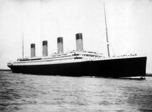
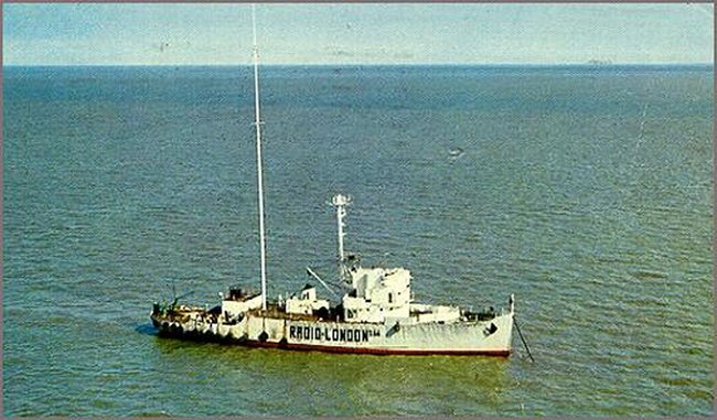
At one time there were several ships out there in the English Channel and coastal Denmark. The first and best-known of these was Radio London or “The Big L.” It broadcast on 1133 KHz from December 16, 1964, to August 14, 1967, using a 50,000-watt RCA ampliphase transmitter. The ship itself was the M/V (motor vessel) Gallaxy, a converted WWII minesweeper formerly known as the USS Density. After Radio London went off the air, the ship was transferred from port to port until it ended up in Kiel, Germany, where it was finally scrapped in the late 1990s.
Radio Caroline was the main offshore competitor, broadcasting on 1520 KHz and several other frequencies off and on from 1964 until 1990 or so using several different vessels to transmit from.
One incident in offshore broadcasting that has always fascinated me was the burning of the Mebo II, then transmitting Radio Northsea International off the coast of Holland (this ship moved around quite a bit) in 1971. Later investigations revealed that the staff of an offshore competitor, Radio Veronica, was responsible for the firing of the ship. Apparently, in those days the competition was brutal.
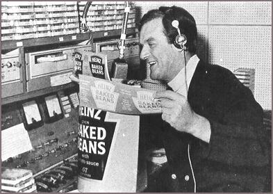
I like the nice calm music with the increasingly frantic DJ (West, no East). In any case, the ship remained afloat and returned to the air the next day. The final European offshore broadcaster was something called Laser 558 on M/V Communicator. It broadcast using to CSI 25 KW AM transmitters on 558 KHz in 1983, again, off and on for several years until 2004. The CSI-grounded grid transmitters may have been inexpensive to purchase, but I’ll bet they cost a lot to run. This would be especially true if one were using diesel generators as the main electrical power provider. As a result, they were usually run at about 1/2 power. Eventually, M/V Communicator ended up beached in the Orkney Islands off of Scotland.
The only such attempt in the US was Alan Wiener’s MV Sarah, known as “Radio Newyork International” anchored off of Jones Beach on 1620 KHz. The owners figured 4 miles offshore was far enough to be in international waters, but the FCC felt otherwise, I believe at the time, 12 miles was (and still is) the territorial limit for the US. Four miles was not international waters, as the broadcasters claimed. These guys were arrested and sent to trial. After several years all charges were dropped.
Anyway, an interesting bit of radio history. Goes to show the lengths that some will go to when feeling repressed.