This is one of my favorite old transmitter memories. Back when I landed my first Chief job, I was working for an AM/FM combo. The AM station was a 50,000-watt flame thrower that first went on the air in 1947. The original transmitter, a General Electric BT-25-A was still in service as a backup unit. These pictures are from the last night it operated, December 16, 1993. The bank made us remove all of the PCB transformers and capacitors before they would refinance their loan. Of course that was most of the transmitter, the rest of it was scraped or sold for parts.

The transmitter takes up the entire span of the room. There were eight large cabinets, each with its own stage or section. The stages were connected to each other by a wiring trough in the floor. The transmitter used lead-jacketed cable within and between sections.
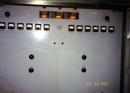
The IPA section had been modified to use 833A tubes. This is where the RF was developed and amplified for the final section. It is in the middle cabinets of the transmitter, the audio and control section being to the left, the PA and PA power supply being to the right.
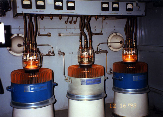
Final section. There were three tubes, only two were in use at any given time. The third tube was a spare which could be quickly placed in service by throwing a knife switch and moving those bars on the back wall around. This picture was taken with filament voltage only, we had to close the door to turn on the PA voltage.

The transmitter was cooled by this blower which faces down into the floor. Concrete duct work carried the air to the various stages of the transmitter. The blower is powered by a 2 1/2 HP motor. There were two blowers, one in use and one in standby. Behind this is an air mixing room and filter room. During the winter time, the transmitter waste heat was used to heat the building by closing a series of ducts and opening other ones.
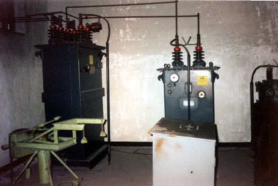
This is in the transformer vault. The unit to the left is a modulation transformer, it was 7 feet tall. Directly in front is the modulation reactor and just out of the picture to the right is the plate transformers. The plate supply was 480 volts 3 phase. The other piece of green equipment is a hydraulic tube jack, to get the 5891 final and PA tubes out of their sockets.
The transformers were what contained most of the PCBs. The modulation transformer contained about 150 gallons of Pyranol, the GE trade name for their transformer oil. Pyranol contained greater than 750,000 parts per million PCB.
It is a shame we had to kill this transmitter, it sounded wonderful on the air. The day we signed it off, there was nothing like it, not the Mw-50B that replaced it, nor the Nautel ND-50 that replaced the MW-50, nor the DX-50 at the competing station across town.
What a shame.