Back in the cold war days, the federal government took emergency warnings quite seriously. So much so that they spent about $2 million in 1972 to build a LF (low frequency) radio station WGU-20, in Maryland designed to integrate into the public warning system. This was known as the “Last radio station” because it was designed to operate after nuclear armageddon. Using the first all-solid-state AM transmitter designed by Westinghouse, the station transmitted on 179 kHz (power 50 KW) with a loop that stated:
“Good evening. This is WGU-20, a defense civil-preparedness agency station, serving the east-central states with emergency information. Eastern Standard Time seventeen hours, twenty minutes, twenty seconds.”
The greeting would change to “Good Morning…” or “Good afternoon…” as appropriate.
One small problem arose from this system, no one had long-wave receivers. The government attempted to persuade manufacturers to market, and the public to purchase radios that would only receive periodic tests or that they were likely going to die in the next 15 minutes. It was a tough sell from the start.
Military planners decided that they might integrate the DIDS (Decision Information Distribution System) information gained from surface-to-air radar that would give the approximate impact areas of incoming ballistic missiles. The idea was, the public would then know which areas to “avoid.” It may have appealed to the military mind, but most others didn’t quite see the value in it, especially since reaction times would have been 10 minutes or less.
Plans were to build several of these radio stations throughout the US operating on Low Frequency, which would have replaced the EBS over-the-air daisy chain system that remains in effect today with the current EAS. Unfortunately, the public never bought into the concept, and around 1990 or so, WGU-20 was turned off for good. The nearest thing was to have to it today is NOAA weather (or all hazards) radio.
EBS and EAS have never had to work in a time of emergency and if the circumstances are dire enough for someone to attempt to activate EAS, it is very likely the system would fail.
To any who lives in the capital region, the WGY tower near the intersection of I-90 and I-88 in the town of Rotterdam is a familiar site. It is big, tall, and conspicuously marked with a huge “81 WGY” on the southwest face of the tower. At night the call letters used to be lit up by a spotlight but that may have been turned off in recent years.
In my time as chief engineer there, I found several file folders of memos and other materials about the building of the tower, which started in 1936. Prior to that, WGY used a T-top wire antenna, first from the General Electric plant in Schenectady (1922-25) and then from the current tower site in Rotterdam. Located with WGY were GE’s experimental shortwave stations W2XAF and W2XAD.
When the station increased power to 50,000 watts in 1925, many reports of fading were received from locations 20-50 miles away. WGY engineers studied the situation by doing a full proof on the antenna. They found an elliptical-shaped pattern with nulls to the north and south. This coincided approximately with the T arms of the T top antenna, likely due to the self-resonating effect of the support towers for the ends of the T.
NBC, then owners of WJZ (now WABC) in NYC had studied this problem for years and came up with a new antenna design for Standard Broadcast, the uniform cross-section guyed tower. Starting in 1935, WGY began to investigate installing such a tower in South Schenectady, as the transmitter site was then known. One report showed an efficiency gain of 430% over the T top antenna that was in use. The General Electric construction and engineering department raised several objects to the standard triangular tower then and now commonly used for AM radiators.
WGY transmitting tower, Schenectady, NY
Much mechanical planning and effort went into the design of the tower, which is a square tower, a 9-foot face, 625 feet tall. During the planning phase, KDKA was installing a similar tower, which collapsed when it was being erected in 1936. An analysis of the failure showed that one of the guy anchor cable sockets pulled out of the concrete (which was improperly poured). This may also be the reason why the KDKA tower collapsed in 2003, although I never read the engineering report on that failure. Nevertheless, GE Engineering felt that forging the members of a triangular tower weakens them and was too risky, thus, a square tower was the solution.
Further, every component of the tower was tested individually. Often, two of a type were build, with one being tested to destruction. Two base insulators were made for this specific tower. The first was tested to destruction at the National Standards and Institutes laboratory in Washington DC. It was found that the insulator withstood slightly more than 1,200,000 pounds of pressure. The working load (tower dead weight) of the base insulator is calculated to be about 430,000 pounds, thus almost a 3:1 safety margin.
The wire rope used for the guy wires was also tested to destruction. The working load on the upper guy is about 24,000 pounds, the wire rope broke at nearly 120,000 pounds. The concrete, guy anchor sockets, T bars, and all other parts were likewise tested.
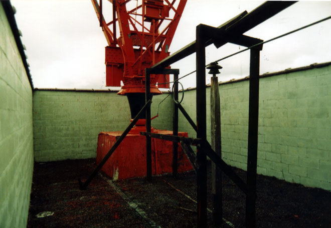
Base insulator, WGY 625 foot square faced transmitting tower
Electrically, the tower is 186 degrees (it was 180 degrees on 790 kHz, the former WGY frequency). It had a 40 X 40 foot ground mat with 120 buried ground radials. The ground radials were #4 hard drawn stranded copper. When we investigated the system in 1999, it was complete and unbroken. The radials, ground screen, strap and all other metal component showed no signs of deterioration. It helps that the soil surrounding the tower is a sandy loam and well drained.
WGY open transmission line between transmitter building and tower base
The tower was fed with 600 ohm open transmission line, 180 degrees long. Initially, the system had been designed for high power operation up to 500 KW. However, when the transmitter was replaced in 1980, a new Harris ATU was installed, which can only handle 50 KW. I recall the base resistance to be 192 ohms with -j85 reactance.
A concrete wall surrounds the base insulator. This was installed in early 1942 to prevent the base insulator from being shot out by sabbators during WWII.
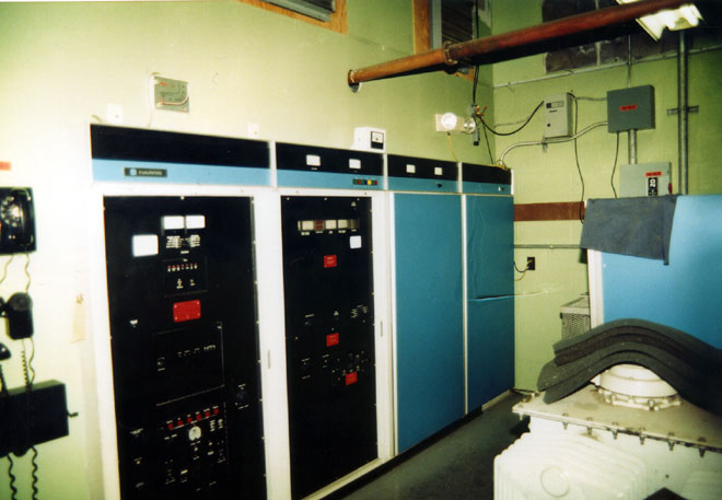
Harris MW-50B, WGY Schenectady, NY
When I worked there, the station had a Harris MW-50B transmitter. This unit was in slightly better shape than its counterpart at WPTR across town. I did find some of the same quirky things with it, however. Our consulting engineer had a good line, “Harris, where no economy is spared…”
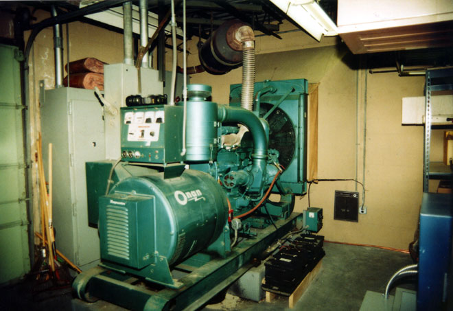
WGY transmitter site backup generator
The site had a FEMA owned backup generator installed in the 60’s. This was an Onan 225 KW diesel powered unit. 225KW is likely a conservative estimate as those units were way overbuilt. The original fuel tank was buried out behind the building. FEMA contracted for it’s removal in 1995 because of concerns of leaks and soil contamination. When they dug it up, the primer was still on the tank. After getting the tank out of the ground, the contractor cut a large hole in it and lowered a person into the tank to clean it out. Something that should be profiled on the Dirties Jobs TV show.
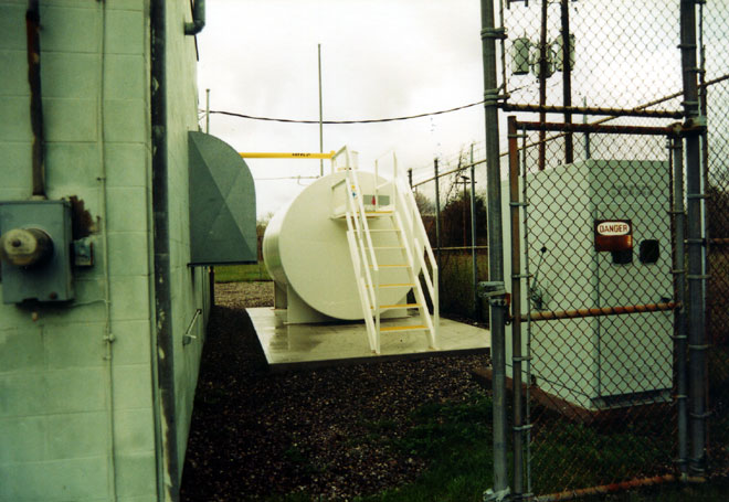
5000 gallon backup generator fuel tank
The new tank was installed in the old outdoor transformer vault. It is a 5000 gallon double walled above ground tank with monitoring system.
It has been several years since I have been to this site. I know they installed a Harris DX-50 sometime in 2001 or so. They also may have replaced the open transmission line. WGY now transmits in HD radio, which they are able to do because the tower was well designed and installed.
File under: Why we check the tower lights every day (or have an automated tower light reporting system):
56 years ago, on September 16, 1953 American Airlines flight 723 flew between the center and northeast towers of the WPTR antenna system while attempting to land at Albany County Airport. The plane crashed about 3/10 mile away near NY route 5 (Central Avenue) killing all 28 persons on board. To date, this is the worst aviation accident in the Albany, NY area.
Several years ago while cleaning out different AM transmitter site, I found a bunch of files about this accident in the trash bin. It seems that some engineer had moved a file cabinet during the great consolidation of the 1990s to the wrong transmitter site. In any case, I rescued the file and for your reading pleasure, have scanned the following documents:
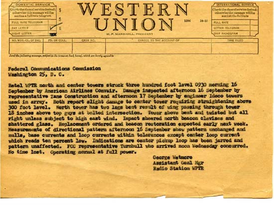
Original telegram to FCC in Washington DC regarding tower/aircraft colision
Retel WPTR north and center towers struck three hundred foot level 0930 morning 16 September by American Airlines Convair. Damage inspected afternoon 16 September by representative Zane Construction and afternoon 17 September by engineer Ideco tower used in array. Both report slight damage to center tower requiring straightening above 300 foot level. North tower has two legs bent result of wing passing through tower 18 inches above top guys at bolt intersection. Tower above bent and twisted but all right unless subject to high east wind. Impact sheered north beacon clevises and shattered glass. Replacement ordered and beacon restoration expected early next week. Measurements of directional pattern afternoon 16 September show pattern unchanged and nulls, base currents and loop currents within tolerances except center loop current which reads ten percent low. Indications are center pickup loop has been jarred and pattern unaffected. FCC representative Turnbull who arrived noon Wednesday concurred. No time lost. Operating at full power
George Wetmore, Assistant Genl Mgr, Radio Station WPTR
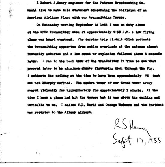
This is the statement of the transmitter engineer on duty at the time of the crash.
Statement from the Engineer on duty at the transmitter site
I, Robert S. Henry engineer for Patroon Broadcasting Co. would like to make this statement concerning the collision of an American Airlines Plane with our transmitting towers.
On Wednesday morning September 16, 1953 I was on duty alone at the WPTR transmitter when at approximately 9:30 A.M. a low flying plane was heard overhead. The carrier trip circuit which protects the transmitting apparatus from sudden overloads at the antenna almost instantly actuated and a low sound of explosion followed about 3 seconds later. I ran to the back door of the transmitter in time to see what proved later to be aluminum sheets fluttering down through the fog. I estimate the ceiling at the time to have been approximately 75 feet and not sharply defined. The centre (sic) tower of our three tower array swayed violently for approximately for approximately (sic) 1 minute. At the time I knew a plane had hit the tower but it was above the ceiling and invisable to me. I called W. R. David and George Wetmore and the incident was reported to the Albany airport.
Back in these days, the studios were located at the Hendrick Hudson Hotel in Troy, the transmitter site was manned by a licensed transmitter engineer whenever the station was on the air.
What is amazing is that the IDECO towers remained standing after being struck by Convair 240, a pretty good-sized aircraft.
American Airlines’ Flight 723 was a scheduled flight between Boston, and Chicago, with intermediate stops among which were Hartford (BDL), and Albany (ALB). The CV-240 arrived at Bradley Field at 06:57. Weather at the next stop, Albany, at this time was below the company’s landing minimums, but was forecast to improve to within limits by the time the flight arrived there. Departure from Bradley Field was made at 07:14. Because of poor visibility at Albany, several aircraft were in a holding pattern. The special Albany weather report issued at 07:50 indicated thin obscurement, ceiling estimated 4,000, overcast, fog, visibility 3/4 miles. Two aircraft left the holding pattern, attempted to land, but both executed a missed approach procedure. A third airplane landed at 08:16 following an instrument approach to runway 19. Immediately following this landing, Flight 723 was cleared to make an instrument approach to runway 19. Three minutes later the flight advised the tower that its approach was being abandoned because the aircraft’s flaps could not be lowered. At 08:30 Albany Tower reported:”All aircraft holding Albany. It now appears to be pretty good for a contact approach from the west. It looks much better than to the north.” Flight 723 was then cleared for a contact approach to runway 10. On finals for runway 10, the Convair descended too low. The right wing of the aircraft struck the center tower of three radio towers at a point 308 feet above the ground. The left wing then struck the east tower. Seven feet of the outer panel of the right wing including the right aileron and control mechanism from the center hinge outboard together with 15 feet of the left outer wing panel and aileron separated from the aircraft at this time. Following the collision with the towers, ground impact occurred a distance of 1,590 feet beyond the tower last struck. First ground contact was made simultaneously by the nose and the left wing with the aircraft partially inverted. The weather reported at the time of the accident was thin scattered clouds at, 500 feet, ceiling estimated 4500 feet, broken clouds, visibility 1-1/2 miles, fog.
PROBABLE CAUSE: “During the execution of a contact approach, and while manoeuvring for alignment with the runway to be used, descent was made to an altitude below obstructions partially obscured by fog in a local area of restricted visibility.”
The above reports notes that the aircraft traveled 1590 feet and struck the ground partially inverted. I do not know what the flaps-up landing speed of a Convair CV-240 is but the cruising speed is 280 MPH. It would be safe to say the aircraft was traveling in the 120 to 130 MPH range or about 220 feet per second. At that speed, it was likely airborne for about 7 seconds after it hit the tower. Enough time to look out the window, realize what was happening, and say “Oh, Shit!”
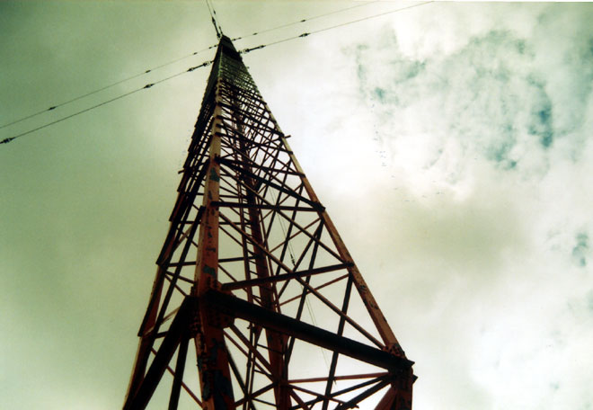
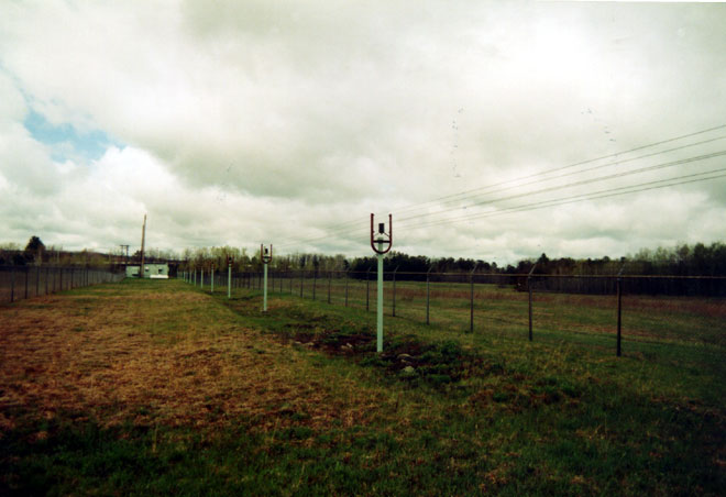
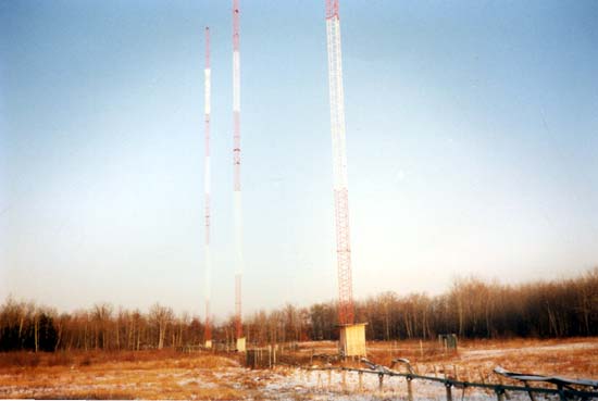
IDECO towers WDCD antenna system, the northeast tower is farthest
IDECO stood for the Internation Derrick Company, they build cranes, derricks, and bridges as well as radio towers. Apparently, they made pretty good stuff because those same towers are still standing today.
Not that checking the tower lights would have averted disaster in this case, it appears to be pilot error compounded by bad weather that caused this incident. But there have been more recent aircraft/radio tower accidents, some of which have involved possible faulty tower lights. I wouldn’t want that on my conscience.
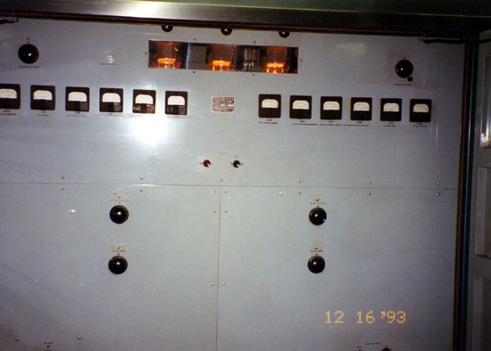
This is one of my favorite old transmitter memories. Back when I landed my first Chief job, I was working for an AM/FM combo. The AM station was a 50,000-watt flame thrower that first went on the air in 1947. The original transmitter, a General Electric BT-25-A was still in service as a backup unit. These pictures are from the last night it operated, December 16, 1993. The bank made us remove all of the PCB transformers and capacitors before they would refinance their loan. Of course that was most of the transmitter, the rest of it was scraped or sold for parts.
This is a long transmitter, GE BT-25-A looking from the control cabinet
The transmitter takes up the entire span of the room. There were eight large cabinets, each with its own stage or section. The stages were connected to each other by a wiring trough in the floor. The transmitter used lead-jacketed cable within and between sections.
IPA stage with “multi-meters”
The IPA section had been modified to use 833A tubes. This is where the RF was developed and amplified for the final section. It is in the middle cabinets of the transmitter, the audio and control section being to the left, the PA and PA power supply being to the right.
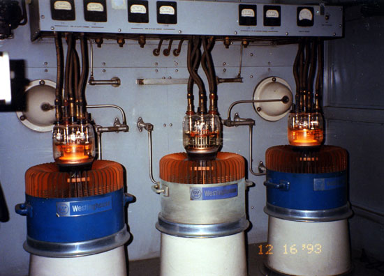
PA section. Those are WL 5891 tubes.
Final section. There were three tubes, only two were in use at any given time. The third tube was a spare which could be quickly placed in service by throwing a knife switch and moving those bars on the back wall around. This picture was taken with filament voltage only, we had to close the door to turn on the PA voltage.
air cooling blower
The transmitter was cooled by this blower which faces down into the floor. Concrete duct work carried the air to the various stages of the transmitter. The blower is powered by a 2 1/2 HP motor. There were two blowers, one in use and one in standby. Behind this is an air mixing room and filter room. During the winter time, the transmitter waste heat was used to heat the building by closing a series of ducts and opening other ones.
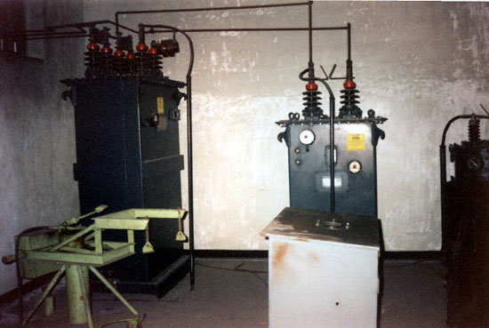
Modulation transformer and modulation reactor
This is in the transformer vault. The unit to the left is a modulation transformer, it was 7 feet tall. Directly in front is the modulation reactor and just out of the picture to the right is the plate transformers. The plate supply was 480 volts 3 phase. The other piece of green equipment is a hydraulic tube jack, to get the 5891 final and PA tubes out of their sockets.
The transformers were what contained most of the PCBs. The modulation transformer contained about 150 gallons of Pyranol, the GE trade name for their transformer oil. Pyranol contained greater than 750,000 parts per million PCB.
It is a shame we had to kill this transmitter, it sounded wonderful on the air. The day we signed it off, there was nothing like it, not the Mw-50B that replaced it, nor the Nautel ND-50 that replaced the MW-50, nor the DX-50 at the competing station across town.