I began fooling around with radios when I was 10 years old or so. First, I built one of those shortwave radio kits from Radio Shack, which was back when they still sold radios.
Then I bought a small tube type AM transmitter at a garage sale. The woman there said her son built it several years ago from a kit and it had the instruction manual. I don’t even know who made the kit. After some experimentation and changing out some tubes, I got the thing to transmit on about 1600 kHz, although it was a little hard to nail down as it drifted quite a bit until everything heated up. I don’t know what power that thing put out, but it was certainly less than a watt.
All of this lead to a brief stint in the military as a radioman. That was an interesting field, albeit different from what I thought it would be when I signed up. It was during this time that I did some part time work at an AM/FM/TV station assisting the Chief Engineer. Once it was established that I actually knew something, my responsibilities grew until I was assigned the AM/FM part of the deal.
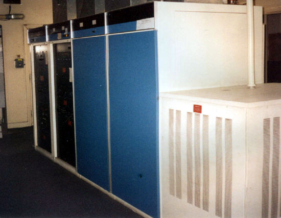
After a year of that, I moved to a different city for family reasons and took the Chief Engineer job at a local AM/FM station. The AM station was a 50,000 watt directional in the high end of the band which had a Harris MW-50B transmitter. My previous station had a Bauer 10,000 D AM transmitter. What could be so different? Plenty I learned, on my second day.

We were subjected to a wicked lightning storm, which, Murphy being present, took out the main transmitter. The backup was a GE BTA25 which was running at half power because of the age of the 5891 final tubes.
The symptoms of the MW-50 where as follows: It would run along fine then there would be a big blue flash and a cannon shot boom, followed by the step start relays cycling and it would come back on the air. There were no overload lights nor any other symptoms leading up to the overload or subsequent to it.
I began by killing the power and shorting out all the high voltage parts with a shorting stick. I noticed that things inside this transmitter where a little unusual, so I got the manual out and started reading. The most unusual aspect of this transmitter is the 25 KV isolated box that the PA stage occupies. 25,000 volts DC is a great big potential and what I found over the years is that this transmitter needs to be kept very clean. Of course, this unit had not been, and that was a part of the problem.
The other unique aspect of this transmitter is the damper diode, which is required by PDM transmitters to conduct voltage during the negative modulation peaks. If the damper diode breaks down for any reason, the PA supply voltage tries to go to infinity, which is a good deal larger than 25KV and all sorts of problems begin.
To make a long story somewhat shorter, this is the problem I had. The solid state damper diode had one bad section, which was causing all sorts of corona problems during heavy negative modulation peaks. It took a call the Harris factory to determine this. The entire diode assembly needed to be replaced because every section is matched. That cost a couple of thousand dollars as I recall.
While I was working on the MW-50B transmitter, I was not impressed. It seemed a little cheap and flimsy. Later, when I voiced my concerns with the station management, the Harris transmitter salesman stopped by and said I needed to get with the program if I wanted to work in that market. This was a Harris town you see, if you start bad mouthing our products, you’ll be the one to suffer. Well, he retired, I kept looking around for other AM transmitters. Three years later I went to work for the competitor across town. Today that station has a Nautel ND-50.
The MW50 went off the air once every 6 months for the entire time I worked at this station. It was always something different, power supply rectifier, bad PDM board, bad directional coupler, arcing insulator on the isolated box, etc. I began to feel it didn’t like me, and I know I didn’t like it. In fact, you could say I have never really liked Harris transmitter products ever since.
Update: Okay, I left a few things out of the narrative:
The 50 KW air cooled power supply was the light weight version. Most MW-50 transmitters had 100 KW oil cooled supplies. The problem with the 50 KW power supply was it was designed with a zero safety factor. All of the rectifier were running at or near maximum current and voltage. It only took one of 144 diodes to go bad, either short or open, and the whole transmitter would crash. Again, no overload lights or other indications of problems. We later installed air flushing fans in the power supply cabinet to keep things cool and that helped out quite a bit.
The other thing was a DC feedback sample to the PDM card. It seems that if the filaments were turned off before the bleeder resistors took the 25 KV supply to zero, the remaining voltage would be routed to the PDM card via the DC feedback sample, blowing the foil off of the circuit card. We fixed this by installing a gas discharge tube with a series resistor at the connection point for the DC feedback sample.
Then there are the infamous 1N914 diodes in the directional coupler that Dave points out below.
I am sure I am forgetting something else, but you get the idea.


please don’t forget the little signal diodes located behind the power output meter panel. You can buy 10 of them for $1.49 at Radio Shack (I think 1N914), but god forbid one of them shorts following a lightning storm. They were meant to rectify the carrier and provide NEGATIVE feedback to the audio driver to stabilize the system and reduce distortion.
Care to guess what happens when one of them shorts? Signal feedback to the audio stage, and it’s not a pretty sight. Suffice to say when the transmitter is turned on the lights would dim in the rest of the building, but not in the transmitter room! It would be very bright in there.
The PDM Class D power amplifier is very efficient, but with the very high voltages involved with this circuitry, flashover is a major problem. I think many of these problems were corrected in the MW50C, but at these voltages, cleanliness and weekly inspections are paramount. The GE BT-25 had better (larger) high-voltage insulators, the layout was not as compact, and the transmitter (with tubes) was designed to take large faults, whereas, the MW50 was more of a paper design than a field proven design. The original MW50 design used a Federal F-1099 vacuum tube damper diode. I actually think this may have been more reliable with the voltages involved. But, pressure to get “solid state” and trash those old antique energy wasting vacuum tubes, made the MW50B more sell-able.
I took care of an MW-50C3 for quite a few years. The management would not pay for an air-conditioner and for cooling there was this system of blowers that picked up dirt from outdoors and injected it directly into the transmitter.
On foggy mornings the blowers would shove a massive amount of wet air into the transmitter and things went ugly real quick.
Arcing insulators that sounded like shotgun blasts were quite unnerving.
I had three of the pressurized capacitors short over a few years time. I had the typical directional coupler and sampler problems too.
In between failures the transmitter worked quite well with plate efficiency in the 90%s. It was a complicated and somewhat fragile transmitter that was difficult to work on and was hard to trouble shoot especially when the building temperature was 110 degrees.
They built these things to sell to managers, not to station engineers. In fact the previous engineer begged management not to purchase it but Harris would always, always, underbid the others.
I stumbled upon this page looking for details of the PA stage and how it was configured for high efficiency. I know the 3rd harmonic resonator was a big part of that but I know that they did something with the screen grid too. I have in mind a ham radio project and I would like to use some of that technology. If anyone has access to the manual or a diagram I would like to refresh my memory.
My favorite transmitter of all time is the Nautel ND-50.
can i ask you how much is f-1099 diode price ?
I have a MW 50A that is acting stupid. I was hoping that it would continue to work until after March 2nd. Mine has a big blower that blows a lot of air through it. Mine will do 100KW if needed. Felix McDonald showed that to me years ago when I first started working for the station. I will be working on it tomorrow. That is the KAAY 1090 AUX transmitter now. A few weeks ago, we installed a new Nautel NX 50 transmitter. The MW 50 transmitter will show no mercy if one gets stuck in it.
in 1981 I was 19 and worked a summer at CFCN radio,in Clagary they were moving to a new am transmitter site , I had to track and unpack all the parts for a new harris ( you guessed it ) MW-50 transmitter ( the one that had the INFAMOUS DAMPER Diode which cost $ 1800 when it blew which was frequent and hard to get to