Box One

I have been remiss in updating this thing, even for Christmas and the New Year.  It has been a busy time, but also, it seems that there is nothing exciting to write about.  Continuing on writing about another transmitter installation or studio project seems redundant.

That being said, I have moved into the realm of high quality audio.  I miss that days when a good audio was the general rule, in both home audio and broadcast.  People have become used to crappy .mp3s played through crappy computer speakers or cheap ear buds.

Knowing just enough to be dangerous, I figured I should do a little bit of research before spending a lot of money foolishly.  I discovered that there are gobs and gobs of information on various forums and other places around the intertubes.  Most of it seems to be good, although one has to be careful and backup whatever is out there with science.  There are several books about DIY speaker building, amplifier construction, turntable maintenance, etc.  Picking the thing that I thought would be easiest and lead to the  biggest improvement in my own audio system, I set out to build a pair of speakers.

Most people probably don’t realize this, but there is quite a bit of work that goes into a well designed pair of speakers.  I began by thinking about what the end use will be, which eventually is a single ended tube amp based on a KT88 design.  As such, I figured the efficiency of the drivers was an important detail.  Power handling capability of the driver could be quite low, 30-50 watts or so.  Searching through several speaker manufacture’s web sites, I found a small sized, full range driver that is fairly efficient and has excellent reviews.

The Tang Band W4-1337SDF has a published sensitivity of 89dB/1 watt/1 meter.  Its frequency response is 70-20,000 Hz.  It also has a titanium speaker cone.  There have been many an article written and much ink spilled on metal cone speakers, so I did not quite know what to think of the titanium cone.  I did spend a goodly amount of time reading all of the reviews on this particular driver and decided to take the risk and buy two of them.

Next step was to calculate the proper interior volume of the speaker enclosure for a vented box.  Vented or ported speaker enclosures are generally more efficient than sealed units.  Vented boxes are a little bit more exacting to build correctly.  Again, lots of information available on line, some of it is good.  In the end, I downloaded a free software package called WinISD.

WinISD takes into account all of the Thiele/Small characteristics of the driver and generates  a basic box design.  I looked at the proposed box and decided that the internal volume was the important part, the actual shape of the box is secondary so long as it is not an exact cube.  Instead of the 2:3 ratio rectangle, I choose something different; a 1:4 rectangle.
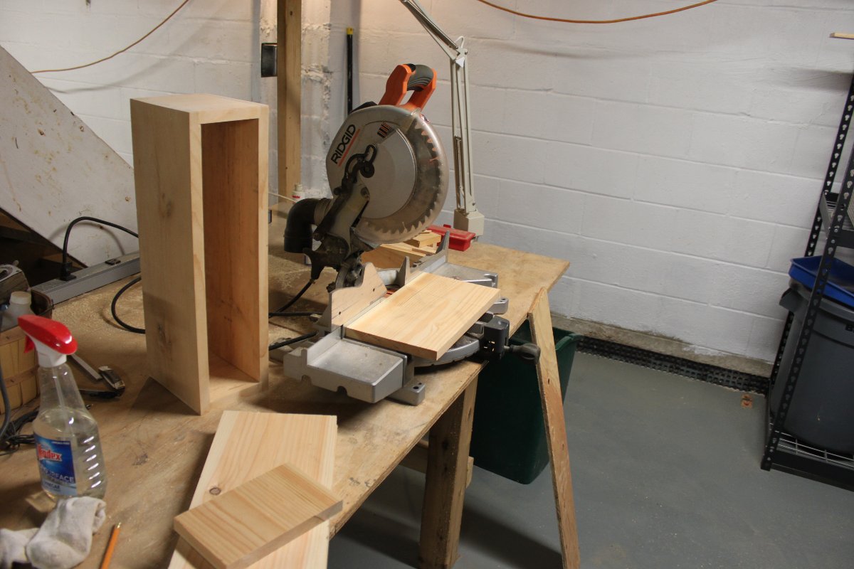
Making cuts for speaker boxes

Next, I began looking around at available materials.  I have plenty of wood laying around from previous projects, so I decided to make the boxes from 1×6 clear pine.  This is also contrary to conventional wisdom, as MDF is the preferred choice in speaker cabinets.  This is because natural wood has a resonate frequency, which can create problems.  As these are low power units, I figured, if it was a huge problem I could always make another cabinet out of MDF.  In the mean time, the wood, glue, paint, screws, foam insulation, tung oil finish where already in the shop.  Why buy more stuff?

I also wanted to add a tweeter (Peerless D19TD-05) to cover the high end and a simple 1 pole (or first order) cross over.
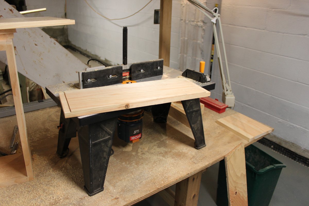
Speaker box work
Speaker box work

Thus, parts ordered, I started working on the boxes.  I decided that rabbit joints where a better choice than mitered 45 degree joints.  I used the router table to make the joints, cutouts and round the cabinet edges.  During the sanding process, I discovered that the wood boxes do indeed resonate somewhere around the 300 to 400 Hz region.  More on that later.

Speaker box glue up
Speaker box glue up

The fronts and backs are made out of 1/2 inch plywood, painted flat black.  There is a one inch rear firing port.  The box itself is larger than what is called for.  I made it thus because there where a couple of different recommendations on box volume and I wanted to add some cross bracing, which takes up space.
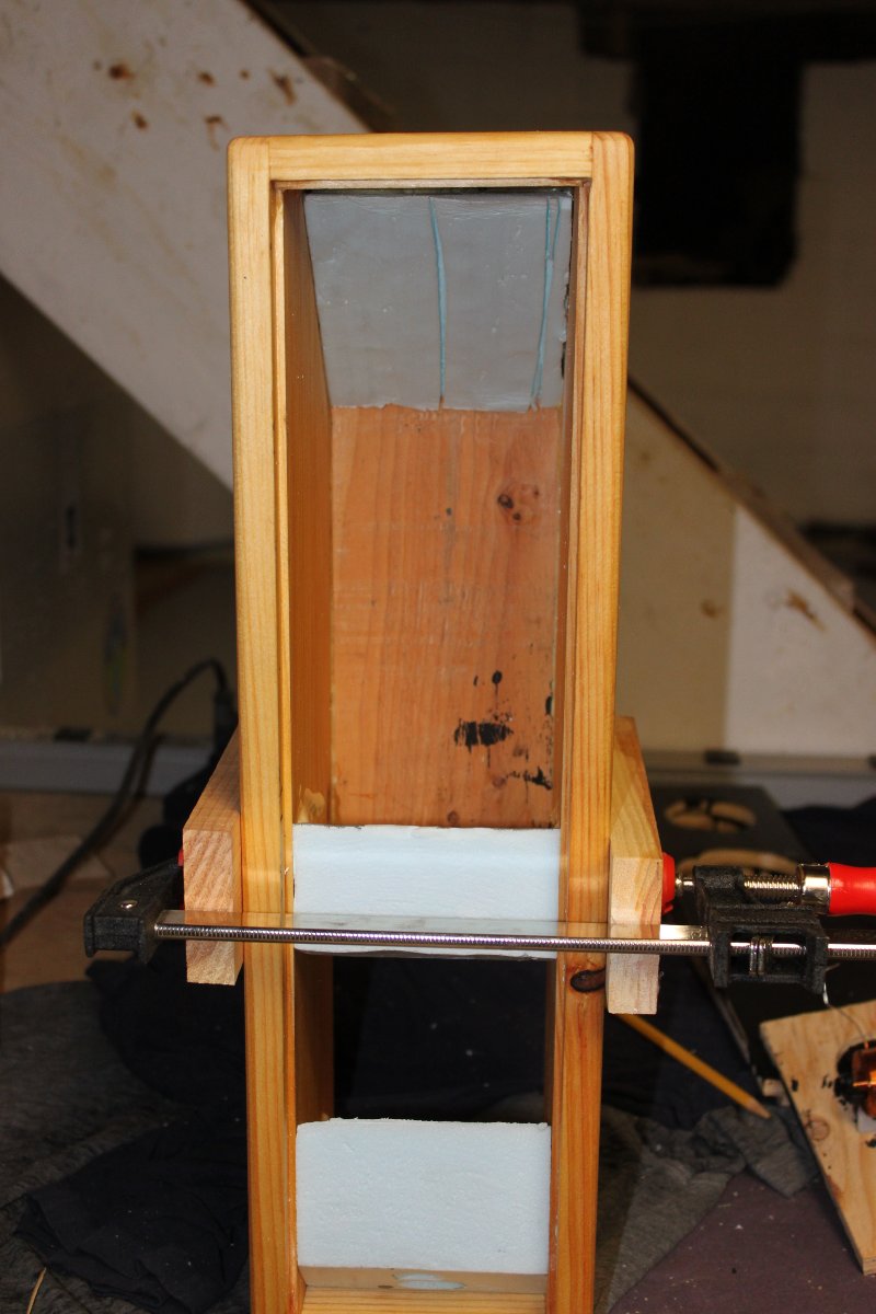
Speaker box, foam dampening and bracing

I thought about ways to dampen the wood box resonance and came up with a bit of rigid foam insulation, again left over from some long ago renovation project.  My idea was to take up some of that excess internal volume, but they might also work to dampen the resonance.  I cut several pieces of this material so that they fit snugly into the box.  I then used the sander to resonate the box and see what effect the foam insulation was having.  In the end, I came up one piece at the top and bottom and one approximately in the middle.  Once I was happy, these were glued in place.  This significantly dampened the resonance.  I also added quite a bit of acoustical foam inside the box.
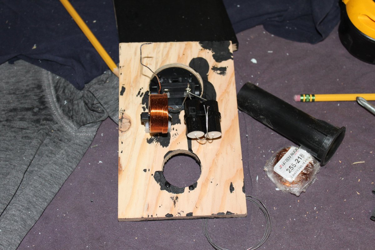
First order crossover

The cross over is designed for 4000 Hz.  It consists of a 5 uF capacitor and a .31 uH inductor.  I am a minimalist at heart.  I thought about nixing the inductor altogether, but I think running both the driver and tweeter at the same time would lower the impedance too much over the high frequencies.
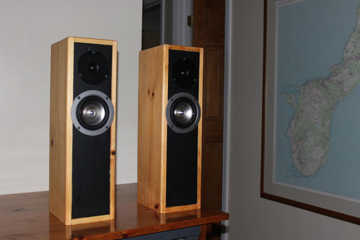
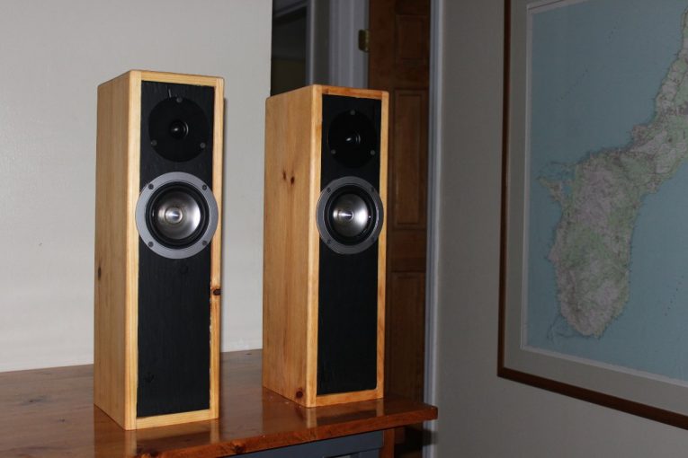
Completed speakers
Completed speakers

The completed project was bench tested using a software program called DATS:
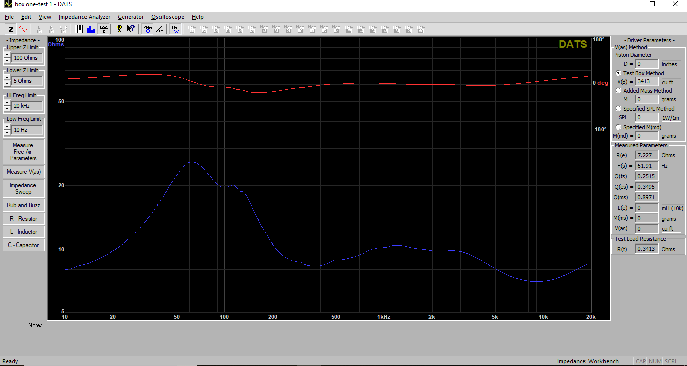
Speaker impedance sweep

The Tang Band driver is resonant at 60 Hz or so.  After the F3 frequency, calculated to be 101 Hz, the impedance looks good all the way out to 20 KHz.  It appears the F3 frequency is slightly higher, likely because the port is too short.

I messed around with the internal box volume by adding and taking away pieces of foam insulation.  In the end, I found that the original volume calculated by WinISD worked (and sounded) the best.

I set these up and took a listen.  Using a reference recording of Tschaikovsky (piano concert #1, B flat minor) I found these speakers sound excellent.  The stringed instruments and horns in particular sound very detailed.  The piano is open and natural.  If I close my eyes, it sounds like it is right in front of me.  Perhaps that is the wood box.  I tried them on several different types of music; jazz, rock and even Tom’s Dinner.  It may be a bit biased, however, I find these speakers to be far and above anything else I have owned in the past.  They sound great.

My only very minor gripe is the bass is not as responsive as I would like.  The low end starts around 90 Hz.  This showed up in the F3 frequency reported by WinISD.  I have a Polk Audio subwoofer that I am using (temporarily) to add the bass back into the mix.  I could also try tuning the ports a little bit to move the F3 down.  That may also require removing some if the foam from the box to increase the internal volume.

I also made a small mistake when cutting the wood for the box, as they are slightly too narrow and the driver does not fully fit onto the plywood front.  That is because I started working on this before I had the drivers in hand.  If I make another pair, I’ll make the cabinet a little bit wider.
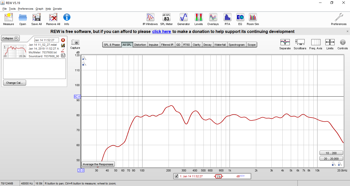
Speaker frequency room response

I also ran a couple of sweeps with Room EQ Wizard.  That 300-400 Hz box resonance shows up in the sweep, but it is not noticeable when listening.  Without the subwoofer turned on, the bass does not start to pick up until about 70 Hz or so, which exactly the spec on the driver.  Funny how that works.
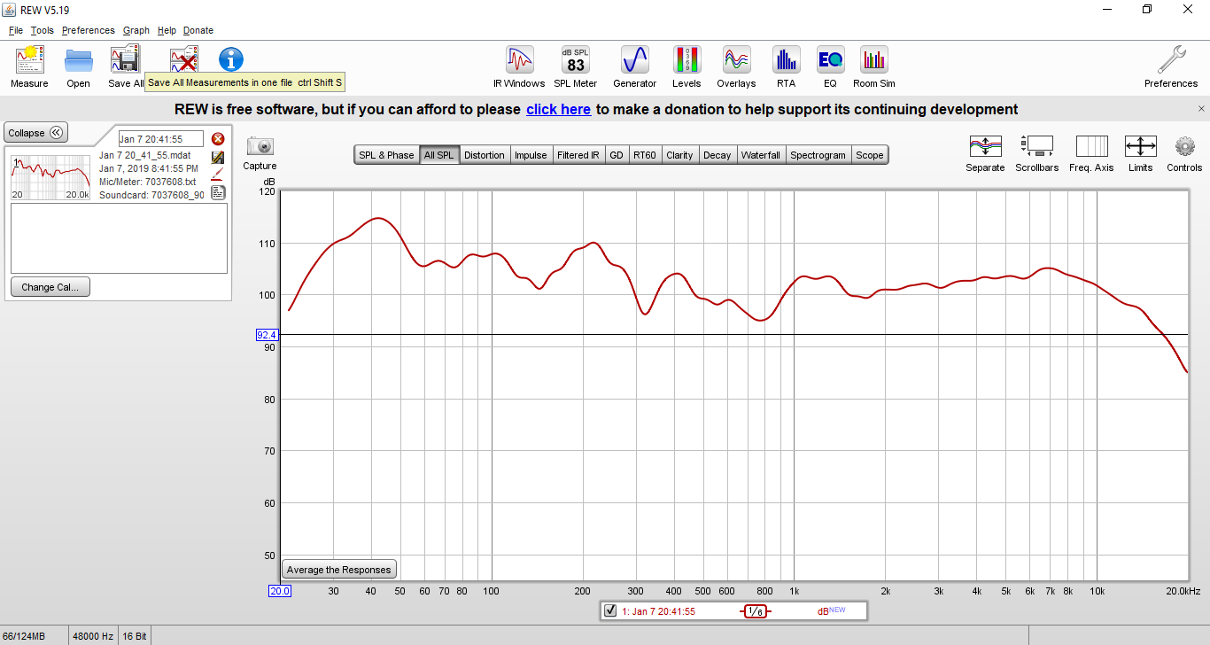
Speaker and subwoofer
Speaker and subwoofer frequency response

This is with the subwoofer turned on. Notice the little hum around 40 Hz, that is the hallway to the bathroom acting as a bass resonator.  Unfortunately, my listening room has some uncurable defects; I cannot get rid of the hallway to the bathroom because eventually that room comes in handy.  I need to get some acoustical material up on the wall and perhaps the ceiling.  I was thinking of a Helmholtz resonator in the wall.
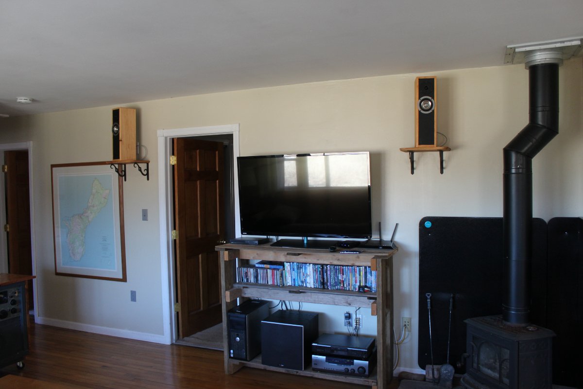
Speakers mounted
Speakers mounted

They sound slightly better if they are moved off axis from the back wall.

My total cost was about $180.00, not counting the materials I already had on hand.  After listening to these for several days, I can say they stack up well against speakers that cost ten times what I paid.

Next project; the matching subwoofer.  I have some ideas…
Happy New Year!

After a bit of reflection and a few good conversations over the New Year’s Holiday, I decided that I should continue my work on this blog.  I would like to thank all those that have stuck by and waited.  I have received numerous emails and messages offline, all of which have been read and appreciated.

Since the abrupt stoppage last July, which was absolutely necessary for me, many things have happened within the business.  Fortunately, during the hiatus, I was still taking pictures.  After sorting through them, here are a few interesting things that happened:

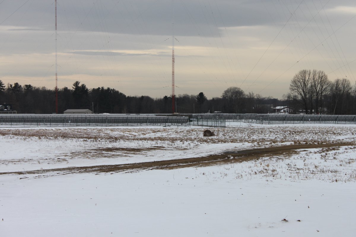
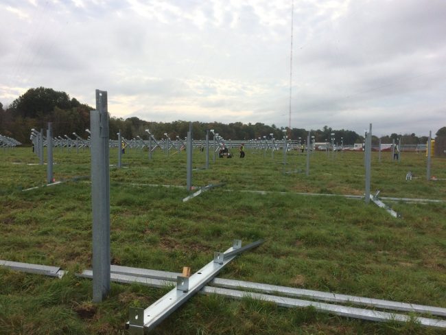
At one of our client’s AM transmitter sites in Albany, NY a 2.6 Million Watt solar system has been installed.

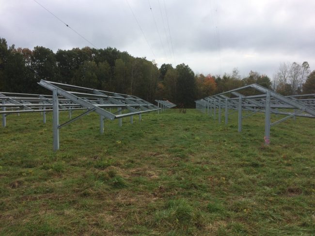
WROW-AM Steel mounting poles on antenna array field

This project required many steel mounting posts to be driven into the ground around the AM towers.  I don’t even know how many, but I would hazard a guess of over three hundred.  Each one of those mounting posts was hand-dug down a depth of 6-10 inches to look for ground wires.  Where ever a ground wire was found, it was moved out of the way before the post was set.

WROW-AM ground wire moved out of way

Basically, the solar array covers about 1/2 of the antenna array field.  All of the steel mounting hardware is tied into the ground system, making, what I am sure is a pretty large above-ground counterpoise.

WROW-AM solar panel mounting hardware

View from the south looking north:

Solar Array installed on WROW antenna array, Glenmont, NY

View from the north, outside of the transmitter building, looking south:

Solar Array installed on WROW antenna array, Glenmont, NY

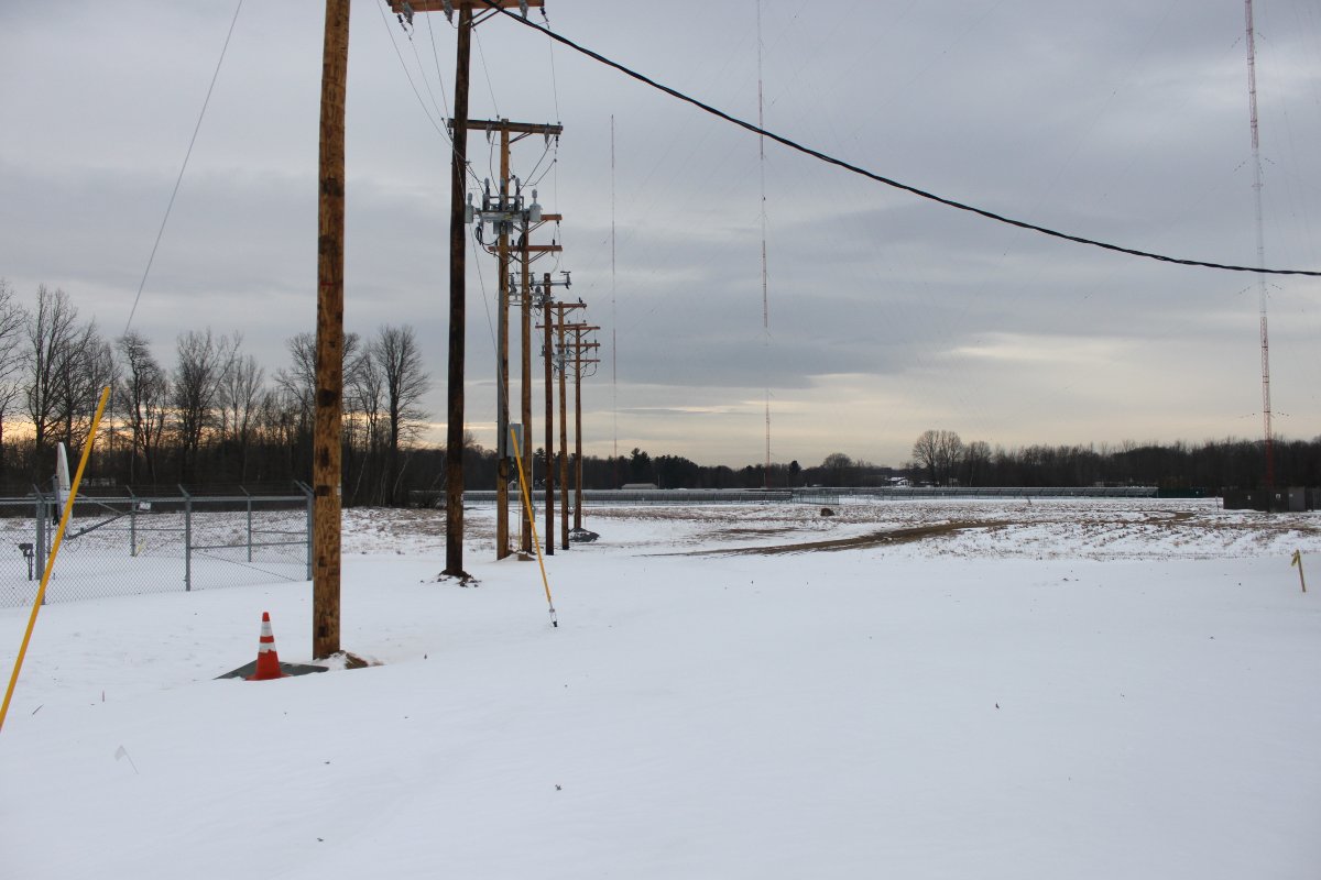
Power company interface and disconnect:

Solar Array utility company disconnect, Glenmont, NY

The utility company had to upgrade the transmission lines to the nearest substation to handle the additional power produced by the solar system. All in all, it was a fun project to watch happen.

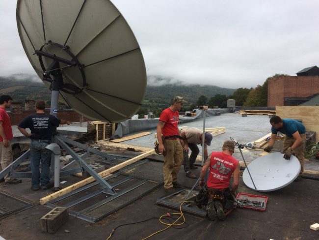
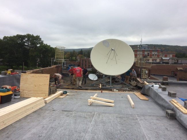
At a certain studio building, which is over 150 years old, the roof needed to be replaced.  This required that the 3.2-meter satellite dish and non-penetrating roof mount be moved out of the way while that section of the roof was worked on.

3.2 meter satellite dish

Dish was ready to move, and all of the concrete ballast was removed and taken down from the roof.  The roofing contractors constructed a  caddy and the entire dish and mount were slid forward onto the area in front of it.  Since the front part of the roof was not reinforced to hold up the satellite dish, we did not ballast the mount and the XDS receivers ran off of the streaming audio for a couple of days until the dish was put back in its original position.

3.2 meter satellite dish ready to move

A couple of other studio projects have been underway in various places.  Pictures to follow…
One of our clients sold their radio stations to another one of our clients.

There has also been a bankruptcy of a major radio company here in the good ol’ US of A.  Something that was not unexpected, however, the ramifications of which are still being decided on in various board rooms.  One of the issues as contractors is whether or not we will get paid for our work.  All things considered, it could be much worse.

Learned a valuable lesson about mice chewed wires on generator battery chargers.  I noticed that the battery charger seemed to be dead, therefore, I reached down to make sure the AC plug was in all the way.  A loud pop and flash followed and this was the result:

Arc burns, right hand

My hand felt a bit warm for a while.  The fourth digit suffered some minor burns.  There is at least one guy I know that would be threatening a lawsuit right now.  Me, not so much…  All of the high voltage stuff we work on; power supplies that can go to 25 KV, and a simple 120 VAC plug is the thing that gets me.

The return of the rotary phase maker.

Rotary phase maker, Kay Industries T-10000-A

Mechanically derived 3rd phase used when the old tube type transmitter cannot be converted to single phase service.

Those are just a few of the things I have been working on.  I will generate some posts on current projects underway.  Those projects include a 2 KW FM transmitter installation, another studio project, repair work on a Harris Z16HD transmitter, etc

It is good to be back!

The GatesAir FLX-40 transmitter

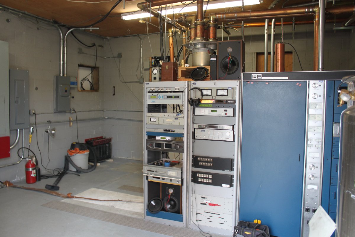
The GatesAir FLX-40 transmitter is my first liquid cooled transmitter installation.  Previously, I have installed an air cooled Nautel NV-40, a V-40 and a couple of BE FM-35T/20T units.  The WEBE transmitter site in Bridgeport, Connecticut is an interesting facility.

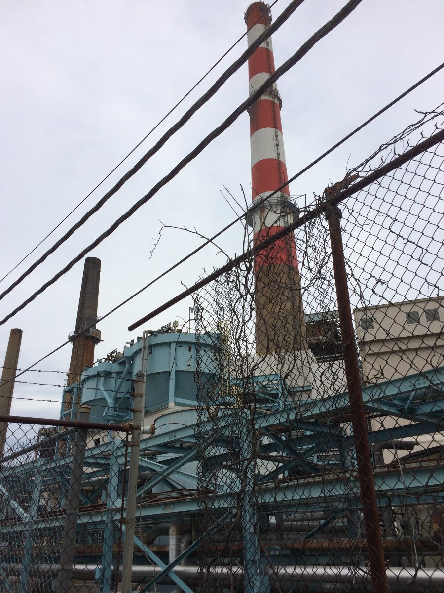
Smoke Stack, Bridgeport Energy, Bridgeport, CT

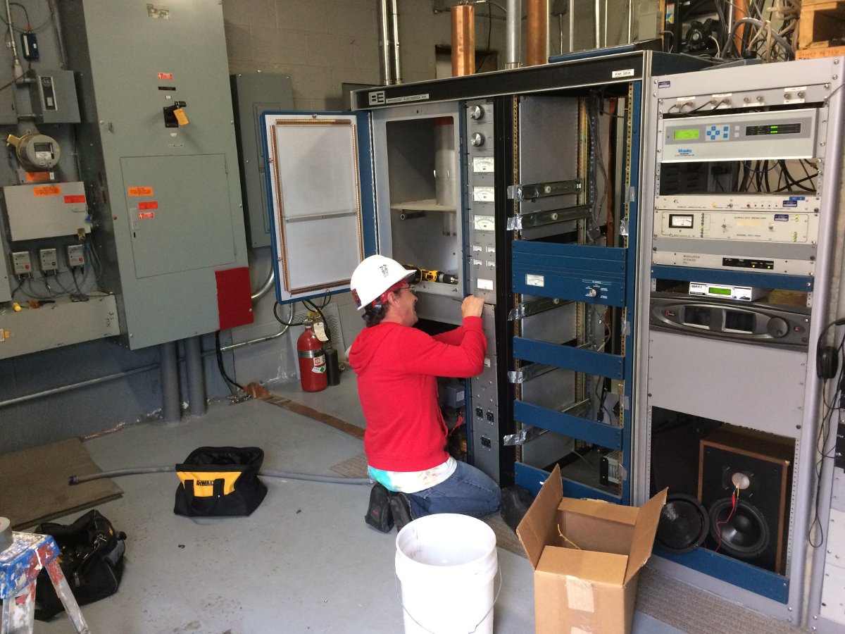
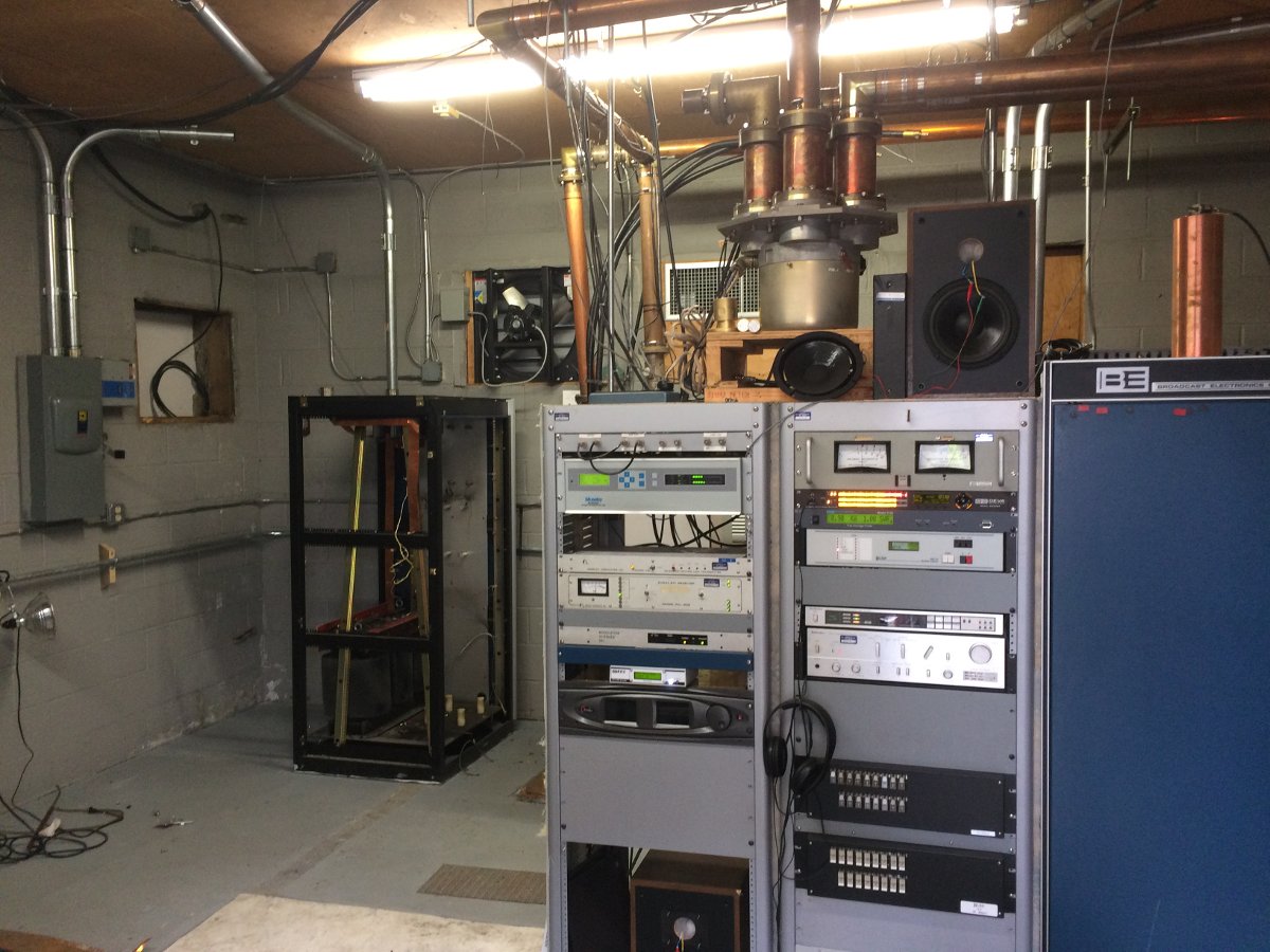
This coal fired power plant smoke stack which currently holds up the six bay, half wave spaced Shively antenna.  The old BE FM35A transmitters are getting little bit long in the tooth.  Thus, we picked one to scrap, the other will be kept for backup service.

Scraping 34 year old BE FM30A transmitter

We saved a whole bunch of parts to keep the other FM35A on the air in backup service.

BE FM30A power supply cabinet

The power supply cabinet with that 500 pound plate transformer was the last to go.

On second thought, that plate supply transformer is a good spare to have

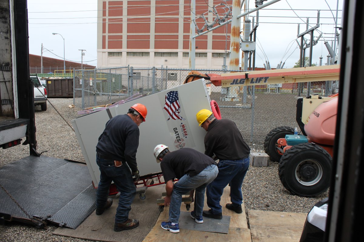
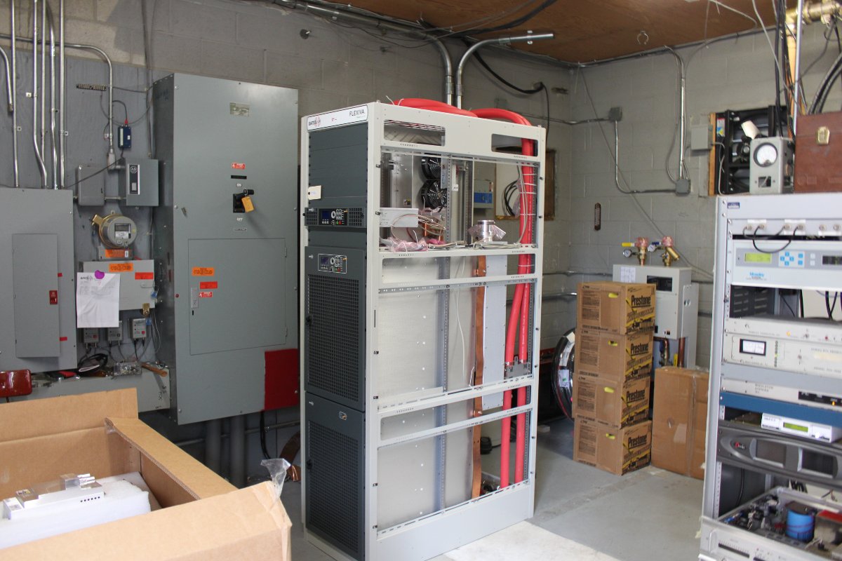
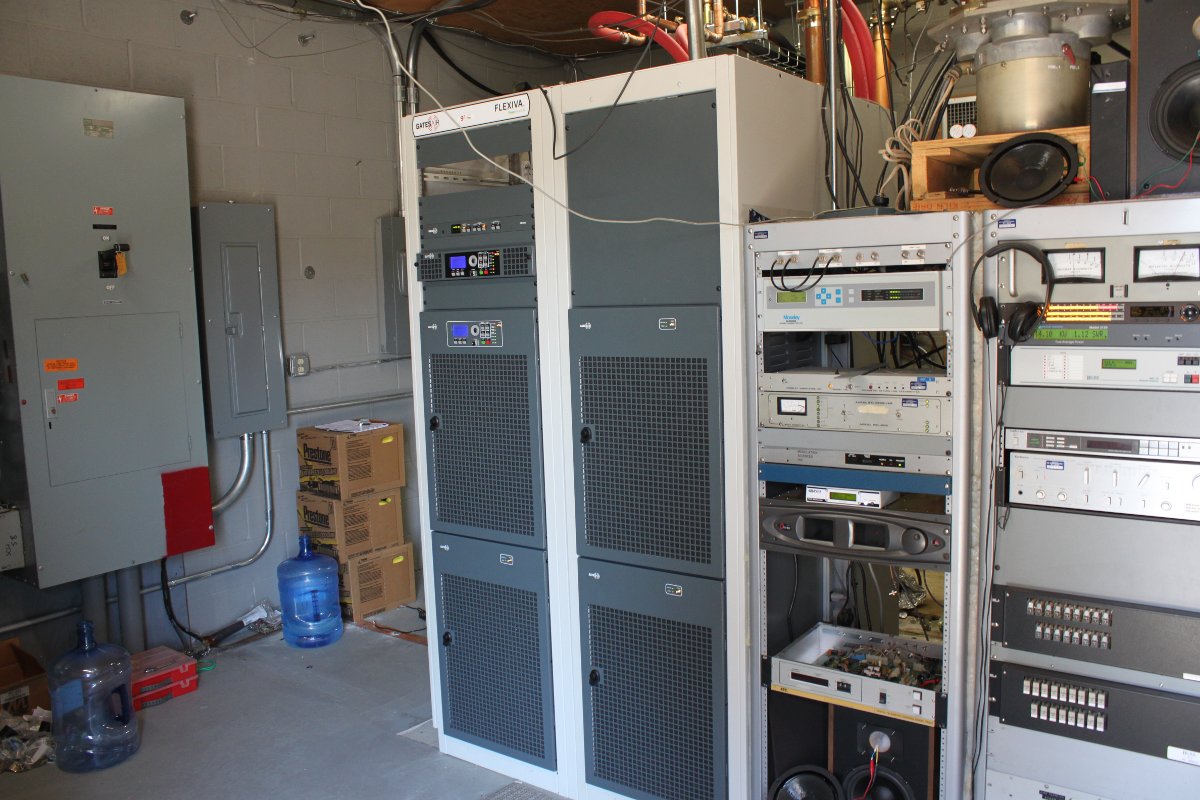
The FLX-40 came on a large truck.  Fortunately, we were able to open the side gate at the power plant and get the truck to the front door of the transmitter building easily.  The transmitter consists of two large cabinets, each with two 10 kilowatt power blocks.  There is also a pump station and an outdoor heat exchanger.

FLX-40 cabinet two off the truck
FLX-40 cabinet one
FLX-40 cabinet one
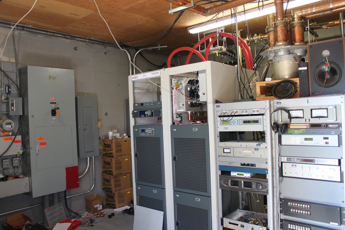
FLX-40 in place, cabinets bolted together

This transmitter design is based on the Harris digital TV transmitters.

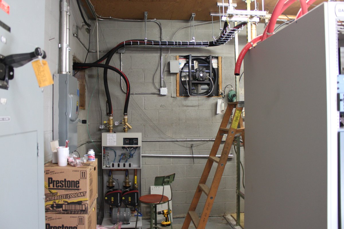
FLX-40 pump station
FLX-40 pump station

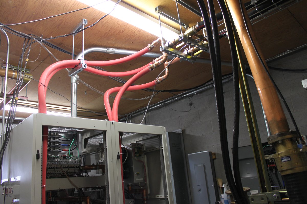
The pump station and heat exchanger are the same systems used for TV transmitters.  Liquid cooled units require a bit more planning on the installation end.  The coolant piping should have a high spot from which everything else slopes down hill.

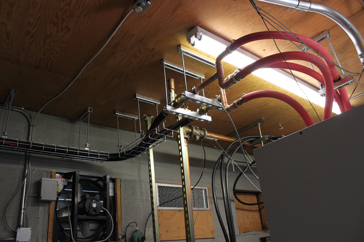
Send and return coolant lines

I put a 1/4 to 12 inch pitch on everything.  Of course, there are several low points, the heat exchanger, pump station and bottom power blocks.

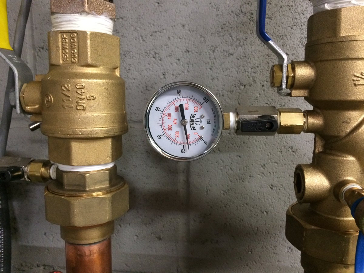
Holding steady at 18 PSI for 24 hours
Holding steady at 16 PSI for 24 hours

After assembling the cooling system, we pressure tested it for 24 hours.

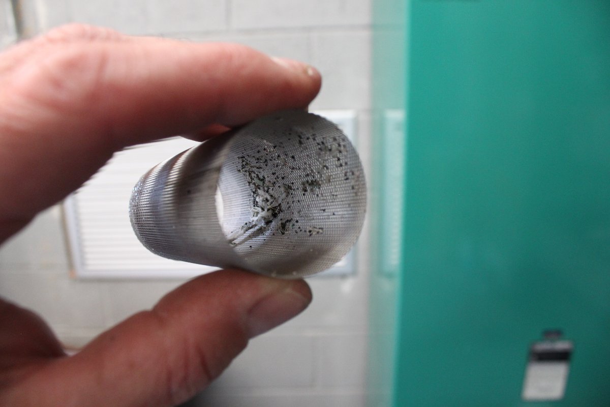
Installation debris in the coolant line strainer

Following that, we flushed the system with distilled water for several hours before we filled it with 40/60 glycol/water mix. Record low temperature in Bridgeport is -7 F (-22 C), thus a 40/60 mix will give protection down to -15 F (-26 C). The more water in the coolant, the better heat transfer capacity it has.

At the highest point in the system, there is a sight glass and an air purge valve

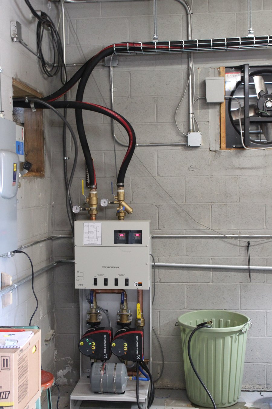
The pump station is controlled by the transmitter, which speeds up the pumps according to how much heat needs to be moved. In turn, the pump station control the fan speed on the heat exchanger outside.

FLX-40 pump station on line

The pump station runs with one motor most of the time. The other pump motor will run in the event of failure or if there is not enough flow through the power blocks. Each of the four power blocks has a flow rate meter on the return line.

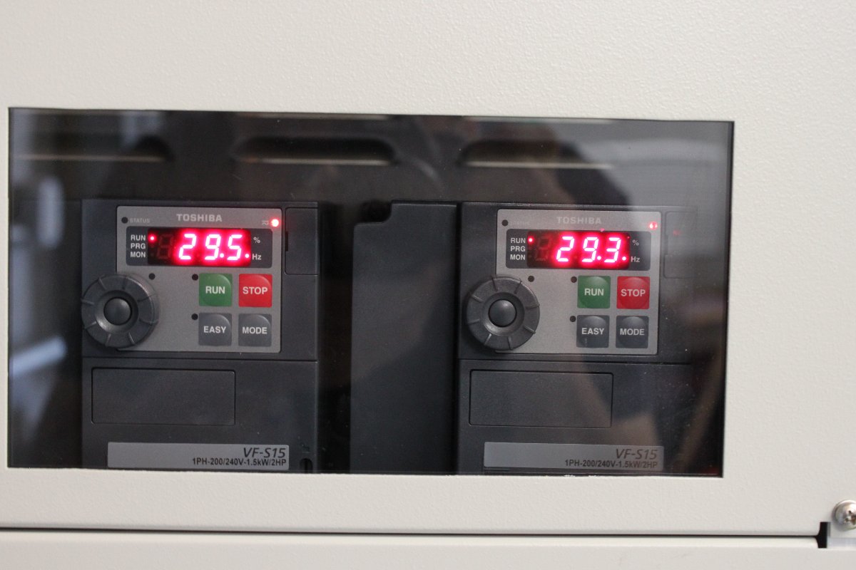
Heat Exchanger Fan motor controllers, Variable Frequency Drive modules

Variable Frequency Drive (VFD) fan motor controllers show them running at half speed.

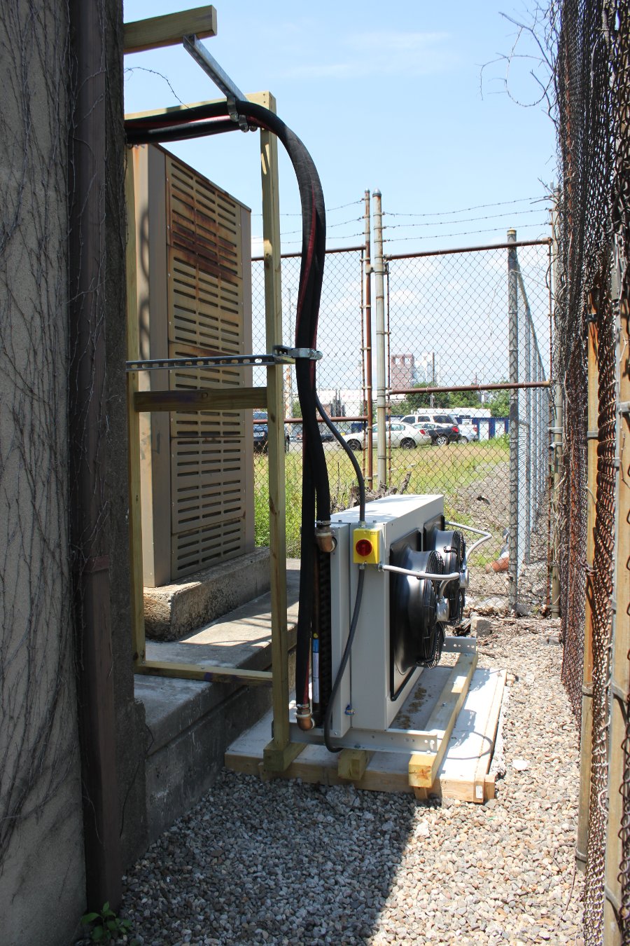
50 KW heat exhanger
50 KW heat exhanger

GatesAir 50 KW heat exchanger mounted on concrete pad behind the building. Air flows out from the motor side.

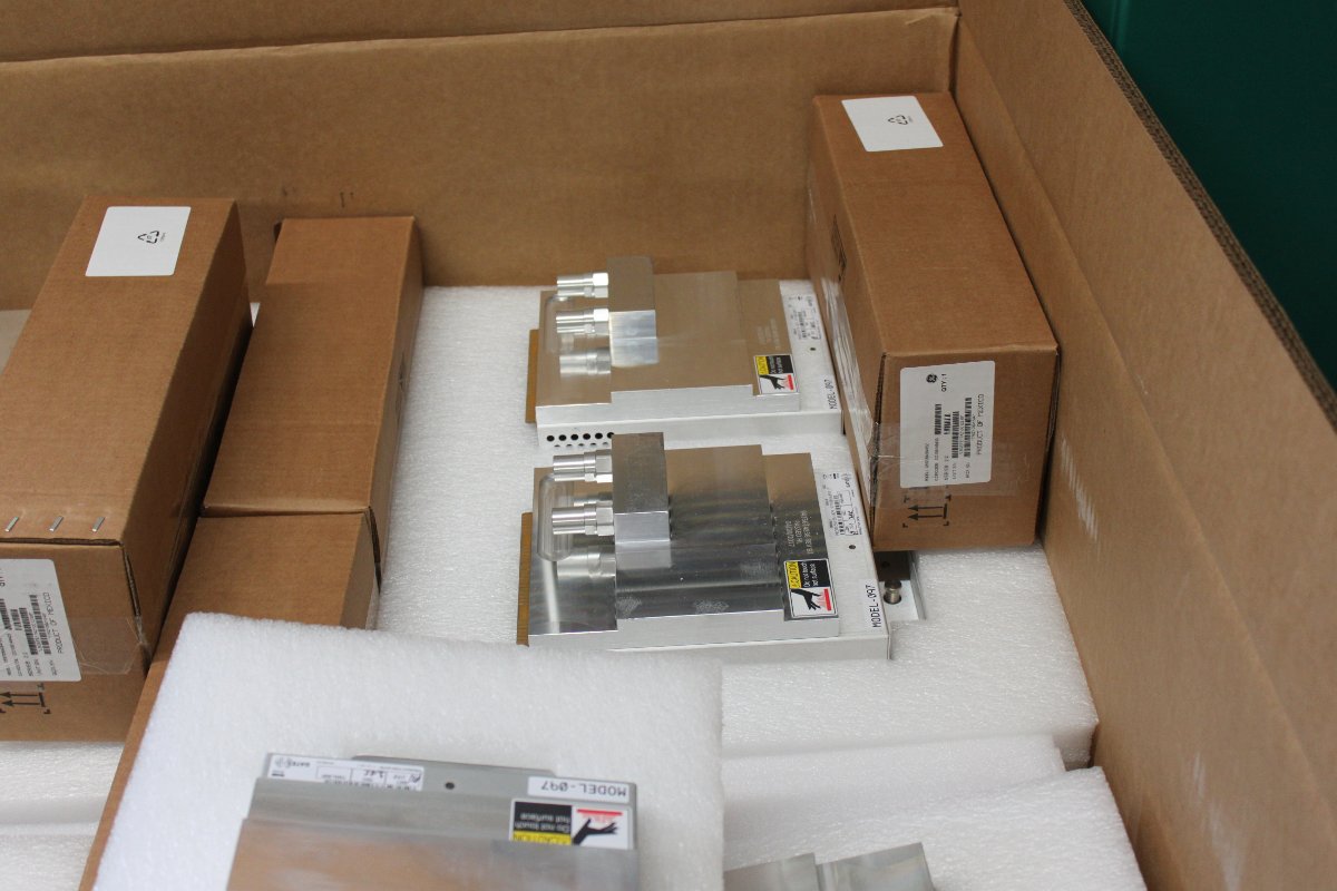
One of several shipping containers with modules and other parts for the FLX-40

As with most things, some assembly required.  The RF modules needed to be placed in the power blocks according to their serial numbers on the test data sheet.  This insures that the information on the test data sheet matches the installed transmitter configuration.  The power combiner between the two cabinets as well as the reject load and directional coupler all need to be installed.

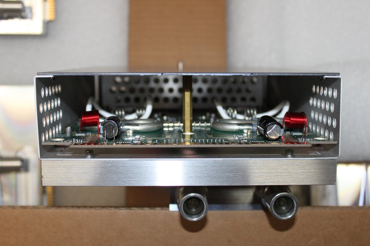
RF modules with large aluminium heat spreaders.   Coolant flows through each module.

FLX-40 power amp module
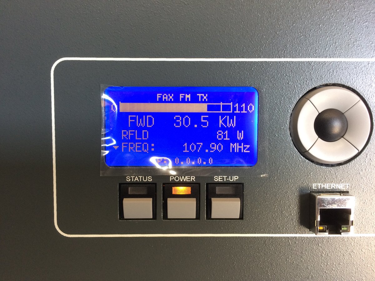
WEBE, Bridgeport, CT GatesAir FLX-40 on the air for the first time

On the air!

FLX-40 into the antenna

We ran the transmitter for several hours into the antenna yesterday afternoon. The coolant system is still purging air, so we periodically needed to add water/antifreeze to the pump station to keep the pressure between 12-18 PSI. Eventually, the TPO will be 34 KW with the HD carrier(s).

All in all, I would say that this was a fun project. The liquid cooled transmitter had a few extra steps during the installation process, but not too difficult.

Hoth

Alternate title: Winter in the Northeast

For all you southerners and west coast people, we have been having an average winter here in the Northeast. While many of our transmitter sites are drive-ups, we have several located at ski area mountain peaks.  Technically, those mountain-top transmitter sites are a fantastic way to get the Height Above Average Terrain (HAAT) way up there.  Logistically, they are much more difficult to deal with.  Installing a new transmitter or even refueling a generator takes major effort.  Working in the cold and wind is much more fatiguing and requires paying special attention to protective clothing, hydration, exposure, etc.

Here are a few pictures from Killington and Pico mountain ski areas in Vermont

Your ride is here.
Your ride is here.

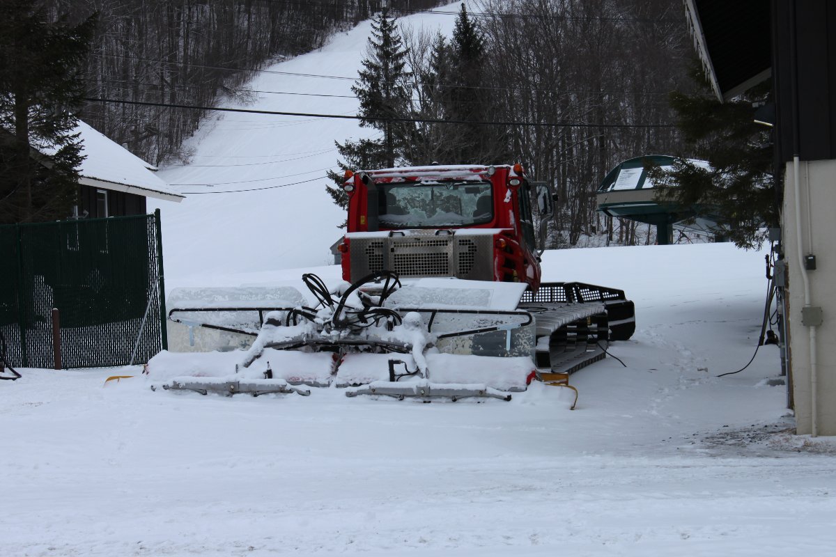
The snow grooming machine is the only way to bring anything up to the top of the mountain during the wintertime. In this case, I needed to replace a BW Broadcast TX 1500-watt transmitter.

Trail from ski lift to tower

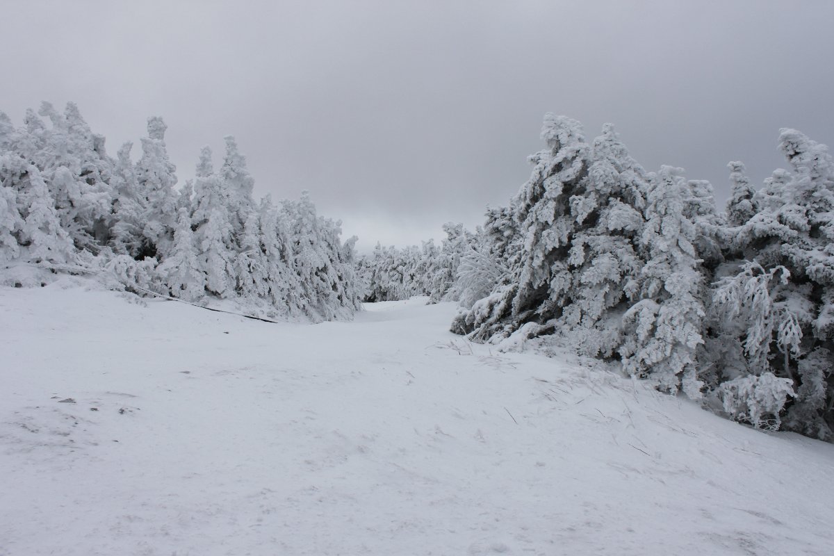
Even with the snow grooming machine, the last few hundred yards need to be walked. Fortunately, the snow is packed and not too deep here.

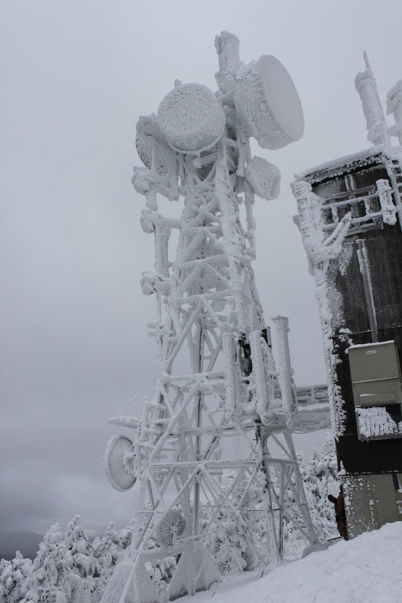
Tower on Pico Mountain

Tower is encrusted with ice. I can tell the tower climber is having a great day:

Tower climber working on ice encrusted towe
Tower climber working on ice-encrusted tower

Riding the chair lift back down the mountain gets plenty of strange looks from those skiers coming up:

Pico chair lift
Pico chair lift

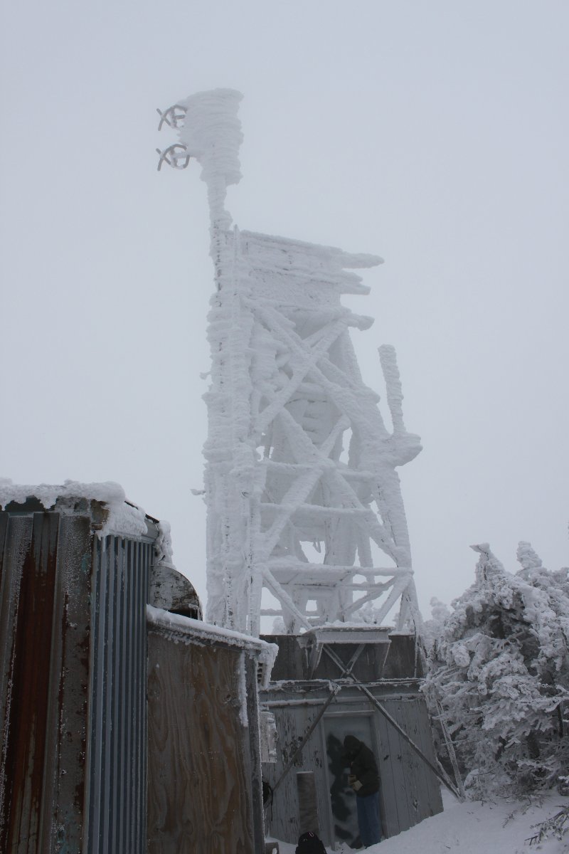
Over on Killington Peak, conditions are actually worse.

Killington Peak tower

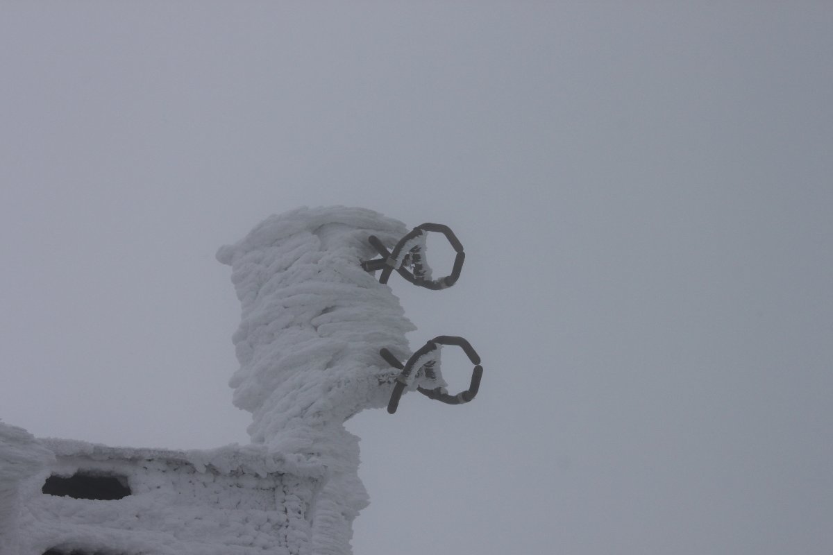
The ERI antenna heaters cannot keep up with the ice buildup.

ERI two bay antenna with ice.
ERI two-bay antenna with ice.

The general manager insists that this winter is not too bad and everything should be working right. My statement to her: Based on my 27 years of experience, your shit is fucked up. But if you know how to fix this, come on up and show me.  She deferred.

FM transmitter building and antenna

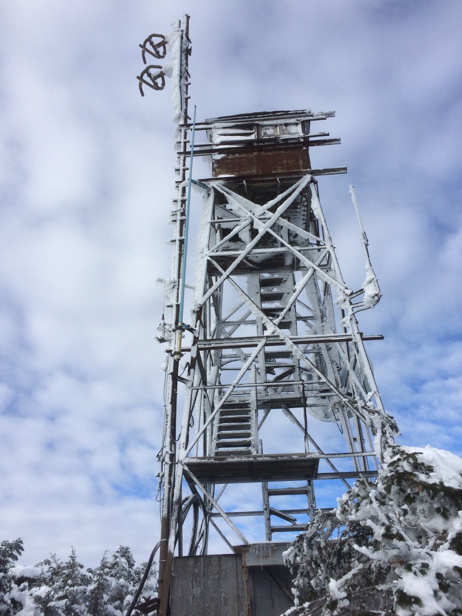
What the fire tower looked like last winter.

Killington peak fire tower

Train from the Gondola to the tower